6-14 Computer Group Literature Center Web Site
Jumpers, Connectors, and LEDs
6
Note To enable this port, you must configure jumper header J5 (see J5
Test/Debug Port Selection on page 6-7).
Parallel I/O Header J13
A 26-pin header (J13 on MBX series boards) provides access to the
parallel I/O interface. The pinouts are arranged to permit a direct ribbon
cable connection to a standard IEEE P1284-A DB25 female connector.
The pin assignments are listed in the following table.
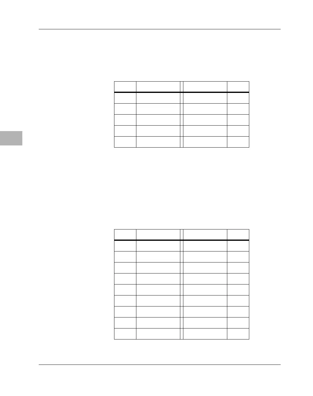
Table 6-5. Debug Port Header Pin Assignments
Pin # Signal Signal Pin #
1 VFLS0 SRESET# 2
3 GND DSCK 4
5 GND VFLS1 6
7 HRESET# DSDI 8
9 +3.3V DSDO 10
Table 6-6. Parallel I/O Header Pin Assignments
Pin # Signal Signal Pin #
1STBO# AUTOFD# 2
3D0 FAULT# 4
5D1 INIT# 6
7 D2 SEL_IN# 8
9 D3 GND 10
11 D4 GND 12
13 D5 GND 14
15 D6 GND 16
17 D7 GND 18

 Loading...


