8xx/COMM Expansion Connectors
http://www.motorola.com/computer/literature 6-17
6
Note If the AUI option is not present on the MBX board, header J20
and other AUI-related parts are not populated.
8
xx
/COMM Expansion Connectors
MBX series embedded controllers support EBX form factor expansion
modules such as PC/104, PC/104-Plus, and 8xx/COMM modules. On
MBX860 boards, the 860/COMM expansion connector (P1), a 144-pin
high-density socket, provides the electrical connection for expansion
modules. On MBX821 boards, the 821/COMM expansion connector (P1)
performs a similar function. The pin assignments are listed in the following
two tables.
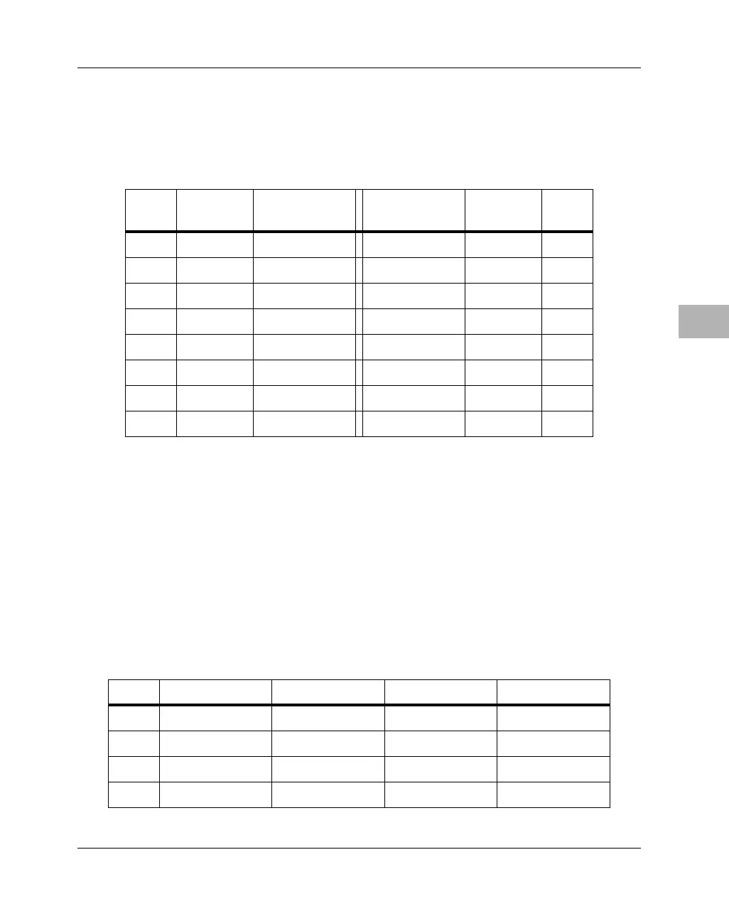
Table 6-9. Ethernet AUI Header Pin Assignments
DB15
Pin
Header
Pin
Signal Signal Header
Pin
DB15
Pin
1 1 GND CD− 29
23 CD+ TD− 410
3 5 TD+ GND 6 11
4 7 GND RD− 812
59 RD+ +12V 1013
6 11 GND GND 12 14
713 1415
8 15 GND 16
Table 6-10. 860/COMM Expansion Connector Pin Assignments
Pin # Row A Row B Row C Row D
1 RETRY# TS# COMMINT# CLKOUT
2 GND GND CS# GND
3 TA# BB# Reserved SPKROUT
4 GND AS# Reserved HRESET#

 Loading...


