PC/104-Plus (PCI) Expansion Connector P2
http://www.motorola.com/computer/literature 6-23
6
PC/104-
Plus
(PCI) Expansion Connector P2
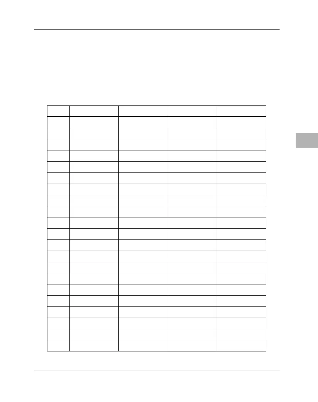
A 120-pin high-speed stackable socket provides an interface for PC/104-
Plus expansion devices. The pin assignments for the PC/104-Plus
connector are listed in the following table.
Table 6-14. PC/104-
Plus
Expansion Connector Pin Assignments
Pin # Row A Row B Row C Row D
1 5V Key Reserved +5V AD00
2 VI/O AD02 AD01 +5V
3 AD05 GND AD04 AD03
4 C/BE0# AD07 GND AD06
5 GND AD09 AD08 GND
6 AD11 VI/O AD10 M66EN
7 AD14 AD13 GND AD12
8 +3.3V C/BE1# AD15 +3.3V
9SERR# GND SB0# PAR
10 GND PERR# +3.3V SDONE
11 STOP# +3.3V LOCK# GND
12 +3.3V TRDY# GND DEVSEL#
13 FRAME# GND IRDY# +3.3V
14 GND AD16 +3.3V C/BE2#
15 AD18 +3.3V AD17 GND
16 AD21 AD20 GND AD19
17 +3.3V AD23 AD22 +3.3V
18 IDSEL0 GND IDSEL1 IDSEL2
19 AD24 C/BE3# VI/O IDSEL3
20 GND AD26 AD25 GND
21 AD29 +5V AD28 AD27

 Loading...


