6-22 Computer Group Literature Center Web Site
Jumpers, Connectors, and LEDs
6
Notes 1. Power Fail Sense# is intended for input and sends a NMI to
the processor when voltage falls below 0.8V. The signal is
filtered for noise.
2. +3.3V, +5V, −12V, −5V, and GND should only be used for
low-power applications.
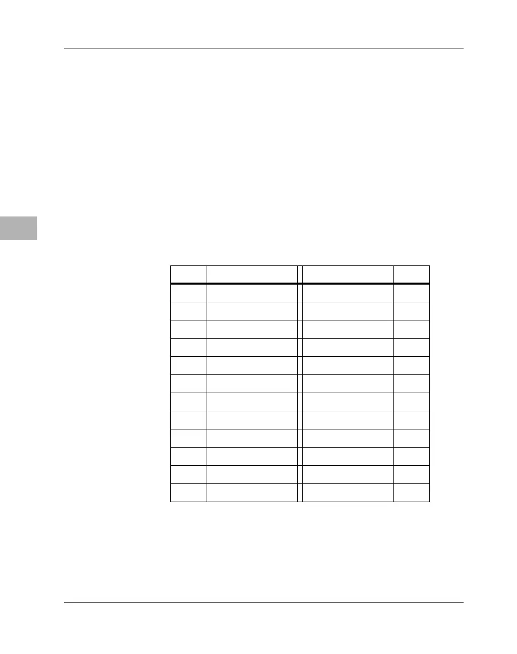
LCD & SPI Connector J27 (MBX821)
On MBX821 models, a 24-pin dual-row header supplies the interface
between the MBX821’s LCD controller and the panel. The pin
assignments for the LCD connector are listed in the following table.
Table 6-13. LCD & SPI Connector Pin Assignments
Pin # Signal Signal Pin #
1GND Reserved 2
3GND SHIFT/CLK 4
5 GND LOAD/HSYNC 6
7 +12V FRAME/VSYNC 8
9+5V LCD_AC/OE 10
11 +3.3V LD0 12
13 LD1 LD2 14
15 LD3 LD4 16
17 LD5 LD6 18
19 LD7 LD8 20
21 SPIMISO SPIMOSI 22
23 SPICLK SPISEL 24

 Loading...


