EasyManuals Logo

Motorola MBX Series User Manual

Motorola MBX Series
116 pages
To Next Page IconTo Next Page
To Previous Page IconTo Previous Page
Page #52 background imageLoading...
Page #52 background image
5-2 Computer Group Literature Center Web Site
Functional Description
5
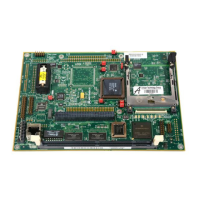
Figure 5-1. MBX821 Entry-Level Features Block Diagram
2142 9802
PIP (SMC2, SPI, TDM)
MPC821
SCC1
PCMCIA
LCD
PPORT Host/Peripherial
Population
Option
Parallel Port
Test Access Port
Ethernet Interface
10BaseT & AUI
Single Slot
PCMCIA
Interface
LCD
Interface
Power
LEDs
RESET
STOP/ABORT
EXT. BATTERY
PWR FAIL SENSE
-5.0V
-12.0V
Clocks
Battery/
KAPWR
Circuits
CS0
CS7
CS1
CS2
CS3
CS4
Chip
Select
Router
FLASH (x32)
Boot
ROM (x8)
DRAM (x32/36)
DIMM Socket (x64/72)
DRAM BANK 1 (x32/36)
DRAM BANK 2 (x32/36)
BBSRAM (x8)
CONTROL & STATUS REGISTER #1 (X8)
CONTROL & STATUS REGISTER #2 (X8)
MPC8XX Interface and Processor Bus
PPORT Host only
MPC821
Local Bus &
Interface
Selector
SMC1
EIA-232
Transceiver
COM1
To/From Standard Version
2142 9802
INFC CNTL
IEEE1149.1
Power
UTILITY CONN #1
Clocks
COMM
Interface
SCC2, SMC1,
I C, CLOCKs, TDM
2
SCC2, SMC1,
I C, CLOCKs, TDM
2
I C
2
SCC2,
SMC1, SMC2, SPI, I C
TDM Signals/Clocks
2
I C
Devices:
EPROM,
DIMM,
DTT
22
Debug Port

Table of Contents

Questions and Answers:

Question and Answer IconNeed help?

Do you have a question about the Motorola MBX Series and is the answer not in the manual?

Motorola MBX Series Specifications

General IconGeneral
BrandMotorola
ModelMBX Series
CategoryController
LanguageEnglish

Related product manuals