6-8 Computer Group Literature Center Web Site
Jumpers, Connectors, and LEDs
6
above as Debug port signals and enables Debug functionality at the Debug
port header (J24 on the MBX board).
The pin assignments of the IEEE 1149 and Debug port headers are listed
in Test Port Header J23 on page 6-13 and Debug Port Header J24 on page
6-13.
For additional details on the configuration and use of the multiplexed IEEE
1149 test port and Debug port signals, refer to the MBX Series Embedded
Controller Version B Programmer’s Reference Guide (listed in Appendix
B, Related Documentation).
J6 Arbitration Mode
The MBX series embedded controller supports an internal and an external
system arbitration mode.
The internal setting allows one extra master besides the processor. On
standard boards, the additional master would be the QSpan PCI host
bridge. On entry-level boards, the additional master would be an add-on
MPC8xx-type daughter card on the MPC8xx bus.
The external setting allows two masters in addition to the processor. The
additional masters would be both the QSpan PCI host bridge and a card on
the MPC8xx bus.
Note Given these guidelines, external arbitration is restricted to
standard configuration boards with an add-on MPC8xx-type
daughter card capable of bus master operation.
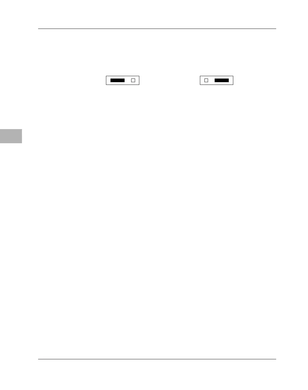
Debug Port Enabled
(factory configuration)
2149 980
J5
1 2 3
IEEE 1149 Test Port Enabled
J5
1 2 3

 Loading...


