6-6 Computer Group Literature Center Web Site
Jumpers, Connectors, and LEDs
6
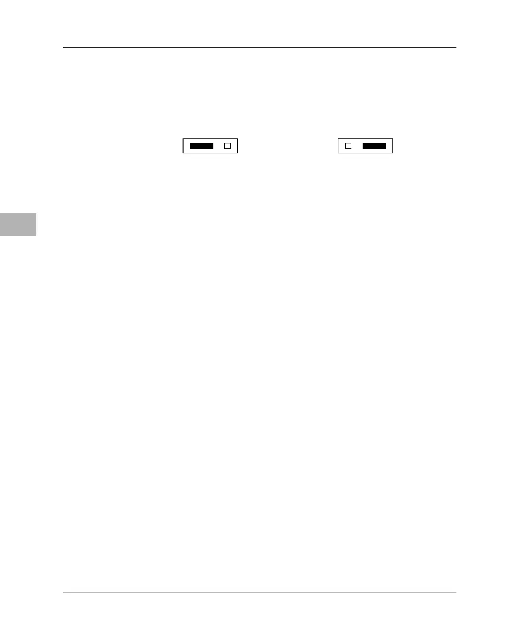
Placing a jumper on J3 pins 1 and 2 disables writes to the device in socket
XU1. Placing a jumper on J3 pins 2 and 3 (the default configuration)
enables writes to the device in socket XU1.
Note To complete the MBX boot device configuration, you must set J4
(boot ROM device selection) on the board as well.
J4 Boot ROM Device Selection
The firmware resident in Flash memory on the MBX series embedded
controller is originally loaded at the factory, but the Flash contents can be
reprogrammed if necessary. For purposes of reprogramming Flash, the
MBX includes a 32-pin socket (XU1) in which firmware programmers can
install a removable boot ROM device. (For information about
reprogramming the Flash, see the MBX Series Embedded Controller
Version B Programmer’s Reference Guide.)
As described under J3 Boot ROM Write Protection on page 6-5, header J3
provides write protection for the device installed in XU1 to prevent
inadvertent overwriting of the Flash memory used in the boot ROM. J4
enables you to select either the soldered Flash memory (x32) or the
socketed Flash chip in XU1 (x8) as the boot ROM. As a secondary
function, J4 defines the bus width of the device selected—8 bits for the
socketed Flash, 32 bits for the soldered Flash.
Boot ROM Write-Enabled
(factory configuration)
2147 9802
J3
1 2 3
J3
1 2 3
Boot ROM Write-Protected

 Loading...


