Serial Port Header J18
http://www.motorola.com/computer/literature 6-15
6
Notes 1. AUTOFD#, INIT#, and SEL_IN# are not supported when
the MPC8xx port is used. They are supported when the
Peripheral I/O controller port is used.
2. BUSY, PERROR, and SEL_OUT are pulled down with
4.7KΩ resistors. All other control signals are pulled up with
4.7KΩ resistors.
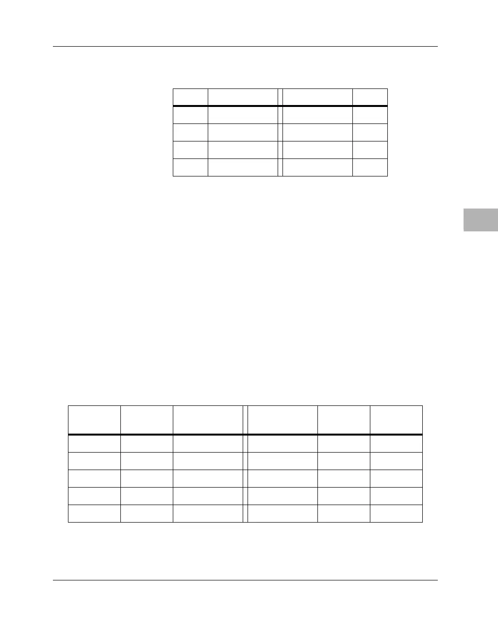
Serial Port Header J18
A 10-pin header (J18 on MBX series boards) provides access to the EIA-
232 serial I/O interface. The pinouts are arranged to permit a direct ribbon
cable connection to a DB9 male connector. The pin assignments are listed
in the following table.
Note For SMC1, only TXD and RXD are supported.
19 STBI# GND 20
21 BUSY GND 22
23 PERROR GND 24
25 SEL_OUT Key 26
Table 6-6. Parallel I/O Header Pin Assignments
Pin # Signal Signal Pin #
Table 6-7. Serial I/O Header Pin Assignments
DB9 Pin
(DTE)
Header
Pin
Signal Signal Header
Pin
DB9 Pin
(DTE)
11DCD DSR 26
23RXD RTS 47
3 5 TXD CTS 6 8
47DTR RI 89
5 9 GND 10

 Loading...


