5-16 Computer Group Literature Center Web Site
Functional Description
5
MBX series boards has the capability to display the Ethernet station
address via the VPD command (described in the EPPCBug Firmware
Package User’s Manual listed in Appendix B, Related Documentation).
Note The Ethernet station address of boards manufactured after March
2000 is $0001AFxxxxxx.
For the pin assignments of the AUI or 10BaseT header on the MBX, refer
to Ethernet AUI Header J20 on page 6-16 and Ethernet 10BaseT
Connector J15 on page 6-16. For programming information, refer to the
MBX Series Embedded Controller Version B Programmer’s Reference
Guide.
PCMCIA Interface
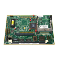
A key feature of the MBX series embedded controller is the PCMCIA bus
incorporated into the MPC8xx processor chip. PCMCIA modules offer a
variety of possibilities for memory expansion and mass storage in addition
to networking applications, wireless communications, and industrial I/O.
The MBX series embedded controller supports one PCMCIA type I, II, or
III module. A 68-pin socket on the base board (XJ26) interfaces with
PCMCIA Revision 2.1-compatible modules to add any desirable function.
For programming information, refer to the MPC8xx bus description in the
MBX Series Embedded Controller Version B Programmer’s Reference
Guide and to the user documentation for the PCMCIA modules you intend
to use.
LCD Interface (MBX821 Only)
MBX boards equipped with an MPC821 processor chip incorporate an
LCD interface controller. The LCD controller has a built-in 256-entry
color RAM. The controller supports both active and passive panels over a
parallel data bus up to nine bits wide. Output control signals are
programmable for polarity and are configurable for a variety of LCD panel
types.
Supplying power circuitry for the LCD panel selected is up to the system
integrator. The LCD controller port routes the data to a 24-pin 2-row

 Loading...