A-2 Computer Group Literature Center Web Site
Specifications
A
Power Requirements
Power requirements for the MBX embedded controller depend on the
configuration of the module. You can determine the power requirements
specific to your application by adding the appropriate values from the
following tables.
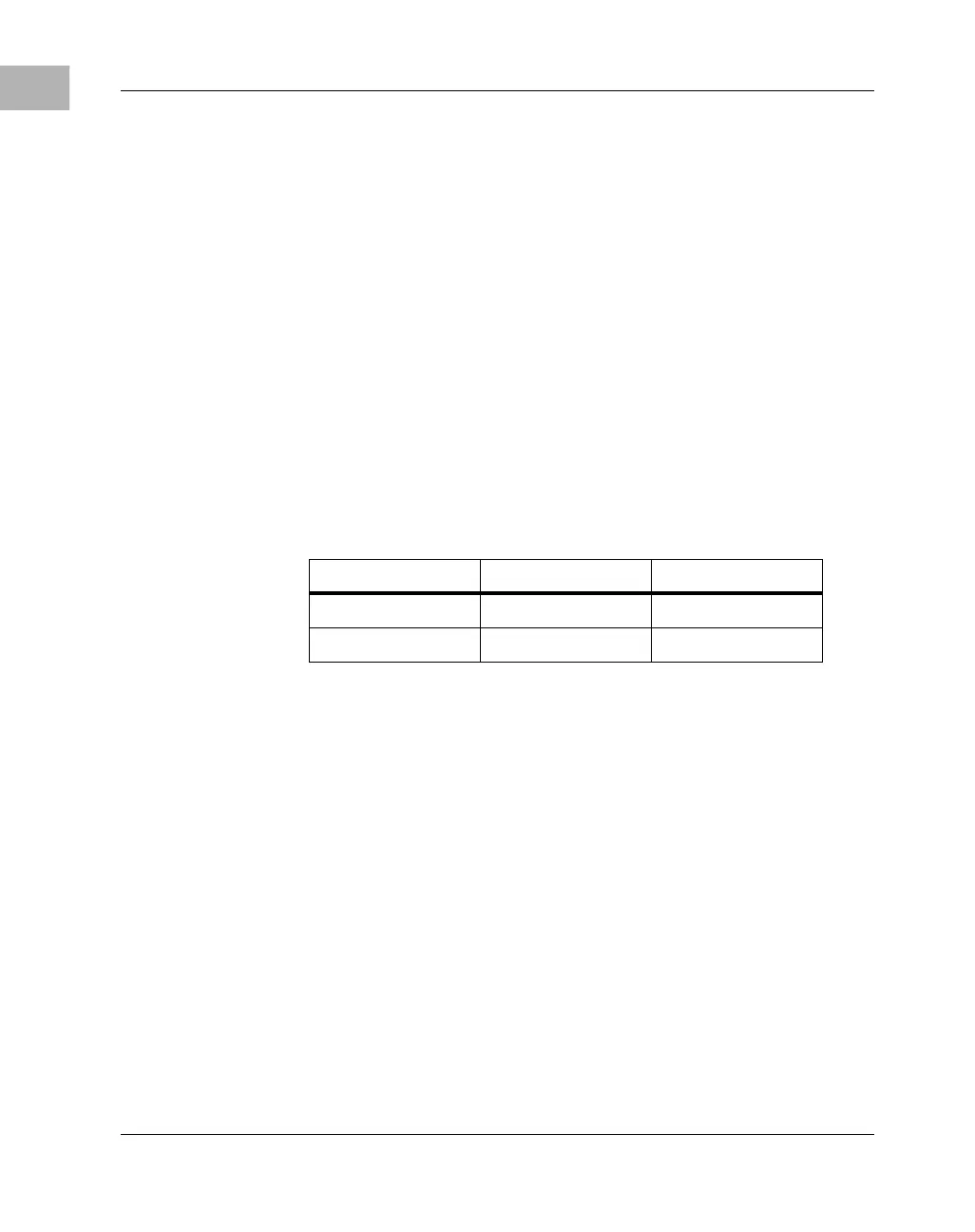
The first table specifies the minimum power consumption of the standard
configuration assuming 16MB of on-board DRAM. The values do not
include power required for expansion modules, expansion DRAM, disk
drives, AUI devices, or PCMCIA devices.
The second table specifies the maximum additional power consumption
expected for each PC/104-Plus module installed, as defined in the PC/104-
Plus specification version 1.0.
Notes 1. It is expected that 5V and 3.3V be supplied to the board at the
same time. To prevent damage to the processor, the 5V
should never exceed the 3.3V by more than 2.5V during
power up or normal operation. For more information, refer to
the “Electrical Characteristics” section of the MPC8xx
processor manuals.
2. +12V power is not used on the MBX board but is supplied
for use by other devices (such as PCI, PCMCIA, and external
AUI transceivers). For the power requirements of these
Table A-2. Basic Power Consumption
Supply Voltage Amps Typical Watts Typical
+3.3V (±10%) 1.0 A 3.3 W
+5V (±5%) 2.6 A 13.0 W

 Loading...


