6-4 Computer Group Literature Center Web Site
Jumpers, Connectors, and LEDs
6
Note MBX series embedded controllers are factory tested and shipped
with the default configurations listed above. The MBX family’s
required and factory-installed debug monitor, EPPCBug,
operates with those factory settings.
J1 Backup Power Configuration
MBX series embedded controllers can use 3.0V–3.6V battery power
(either on board, or external via utility connector #1) as a backup power
source for the “keep-alive” power circuits (such as the real-time clock) in
the processor.
Placing a jumper on J1 pins 1 and 2 (the default configuration) designates
the on-board battery as the source for keep-alive power. Placing a jumper
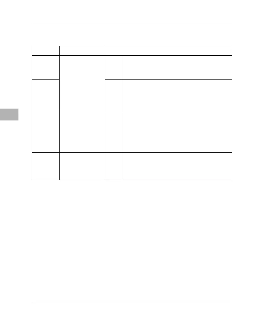
J8 DRAM DIMM
configuration
[1-2] 1M x 64/72 DRAM DIMM (8MB) installed.
2-3 2M/4M/8M/16M x 64/72 DRAM DIMM
(16/32/64/128MB) installed.
J9 [1-2] 1M x 64/72 DRAM DIMM (8MB) installed.
2-3 2M x 64/72 DRAM DIMM (16MB) installed.
none 4M/8M/16M x 64/72 DRAM DIMM
(32/64/128MB) installed.
J10 [none
]
1M/2M x 64/72 DRAM DIMM (8/16MB) installed.
1-2 4M x 64/72 DRAM DIMM (32MB) installed.
2-3 8M/16M x 64/72 DRAM DIMM (64/128MB)
installed.
J11 DREQ# signal
source for DMA-
type PCMCIA
cards
[1-2] PCMCIA module DREQ# signal on INPACK# pin.
2-3 PCMCIA module DREQ# signal on BVD2_SPKR
pin.
Table 6-1. Jumper Settings (continued)
Header Function Jumper Settings

 Loading...


