DRAM
http://www.motorola.com/computer/literature 5-9
5
The processor incorporates a number of other timer functions that, on other
boards, often require external circuits:
❏ Bus access monitor—generates a bus error signal if accesses to the
processor bus are not handled within a programmed time limit
❏ Software watchdog timer—supplies time-out protection in case of
hardware or software module faults (produces a reset if software
does not service a fault within a programmed amount of time)
❏ Periodic interrupt timer—generates interrupts at prescribed
intervals for use with real-time operating systems or application
software
❏ Time base counter—employs the 64-bit counter defined in
PowerPC architecture as a time base reference for operating
systems or application software
❏ Decrementer counter—uses the 32-bit counter defined in
PowerPC architecture to generate a decrementer interrupt
For programming information and details on MPC8xx timer functions,
refer to the MPC821/MPC860 processor user’s manuals.
DRAM
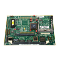
The MBX series embedded controller has provision for either 4MB or
16MB of on-board DRAM, soldered in place. In addition, it
accommodates 8MB to 128MB of expansion DRAM in a 168-pin DIMM
(dual in-line memory module) socket, XU3.
The on-board DRAM is composed of two 16-bit devices (either 1M x 16
or 4M x 16). Parity protection is optional.
If expansion DRAM is installed in the DIMM socket, it must have the same
characteristics as the on-board DRAM, namely:
❏ Single bank
❏ 60ns or faster
❏ 3.3V
❏ Unbuffered

 Loading...