4-2 Theory of Operation
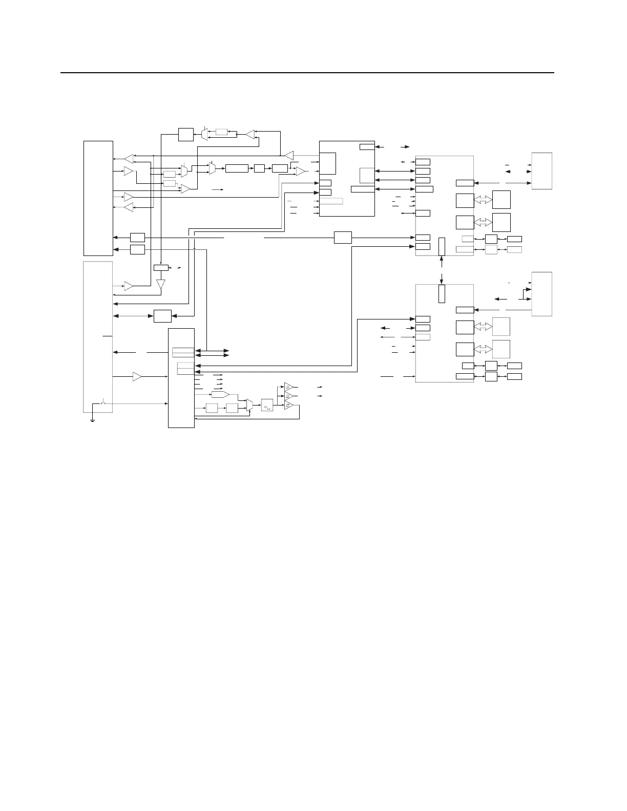
Refer to Figure 4-1 for the MTR3000 Controller Block Diagram.
Figure 4-1 MTR3000 Controller Block Diagram
4.2.1 Tx/Rx OMAP
The Tx DSP is a TI OMAP Multimedia Processor. The OMAP1710 consists of a microprocessor unit
(MPU) subsystem and a digital signal processor (DSP) subsystem.
OMAP1710 has dedicated external memory interface that allow point-to-point connection to
standard mobile SDRAM/DDR and mobile flash devices. It is a low-power device (1.4 V Core and
1.8 V I/O supply). Tx OMAP (U1000M1) handles all transmit tasks of the SCM while Rx OMAP
(U1001M1) handles receiving tasks of the SCM only.
4.2.1.1 External Memory
Both transmit and receive DSP’s support independent external memory banks.
4.2.1.1.1 RAM
The SCM supports Tx/Rx OMAP Mobile Double Data Rate (U1003M1 and U1601M1) SDRAM
respectively. It has the following basic characteristics:
• 32 MB organized as 4 Mb x 16 x 4 Banks
• Four internal banks for concurrent operation
• Programmable burst lengths: 2, 4, or 8 bytes
Add/Data
Add/Data
OMAP1710
Receive
DDR
FLASH
32MByte
16Mx16
32MByte
16Mx16
Receiver
Connector
SSI
OMAP1710
Transmit
Add/Data
Add/Data
Exciter
Connector
SSI
TX
MAKO
McBSP2
EMIFS
EMIFF
McBSP2
EMIFS
EMIFF
SPI
McBSP3M cBS P3
SSI
Abacus SSI
McBSP1CODEC SSI
PORESET
SPIF
PORESET
Back plane
Connector
Rx SPI
Trident SSI
SPIF
32.768KHz
24.576MHz
XTAL32IN
XIN
12MHz
32.768KHz CLK 32K
CLK PLL
MTR2K WL12 & WL34 SSI
USB2
USB0
USB
Front
Panel
+
Rx Audio
CODEC
AUDIO
Mic In
Speaker Out
Audio
Attenuator
I2C
To Tx OMAP
Mic
Tx Audio (PRE)
USB0
USB2
USB-To-
Ethernet
USB
10BaseT Ethernet
(RJ45)
MTR2K Wireline12
SSI
MTR2K Wireline34
SSI
Backplane SPI
Station
Reference
FPGA
Reference In
(BNC)
A/D Inputs
Analog Monitor
I2C
I2C
To Audio Attn
Level
Shift
Level
Shift
RX 16.8MHz
EX 16.8MHz
MCSI1
AUX Rx Audio
UART1
RS232
XCVR
Test
Header
LEDs
LEDs
Power/Status
Tx Status 1
Tx Status 2
Rx Status 1
Rx Status 2
Mode
Ethernet
Ext Ref
FP
G
A
Aba SPI
DDR
32MByte
16Mx16
FLASH
32MByte
16Mx16
+
Limiter
1.0 Vpp Max
Splatter
filter
USB1
I2C
I2C
To WB CODEC
USB
XCVR
Test
Header
UART1
RS232
XCVR
USB1
USB
XCVR
Test
Header
Test
Header
Aux Mi
c
MCSI1
Codec SSI
Reset
To Rx & Tx OMAP
16.8MHz
16.8MHz
TCXO
Charge
Pump
Loop
Filter
Mux
DAC
EX 16.8MHZ
RX 16.8MHZ
32.768KHz
24.576MHz
12MHz
Reset
From FPGA
From FPGA
Reset
12MHz
32.768KHz
CLK 32K
CLK PLL
Control &
Status
GPIO
TX SP IF
RX SP IF
EX/BP SPI
RX SPI
Ex SPI
EX/BP SPI
From FPGA
EX/BP SPI
From FPGA
To Mako and Exciter
To Receiver
RX SPI
From FPGA
FP PUSH
BUTTON RST
Note: MTR2K Wireline is not a suppo
rted feature for Bandit
releases. The circuit will not be replaced and reserved in case of this
requirement changed in the future.
High
Pass
Filter
+
De-
Attn
TOMAP MPUIO0
0
1
Tx Data/PL/DPL
Pre-
Emphasis
Pre-
Emphasis
Emphasis
+
TXOMAP
MPUIO10
0
1
0
1
TXOMAP
MPUIO13
Default Path selected
Tx Audio (Flat)
 Loading...


