3-10 Troubleshooting
3.3.2 Disassembly and Reassembly Procedures
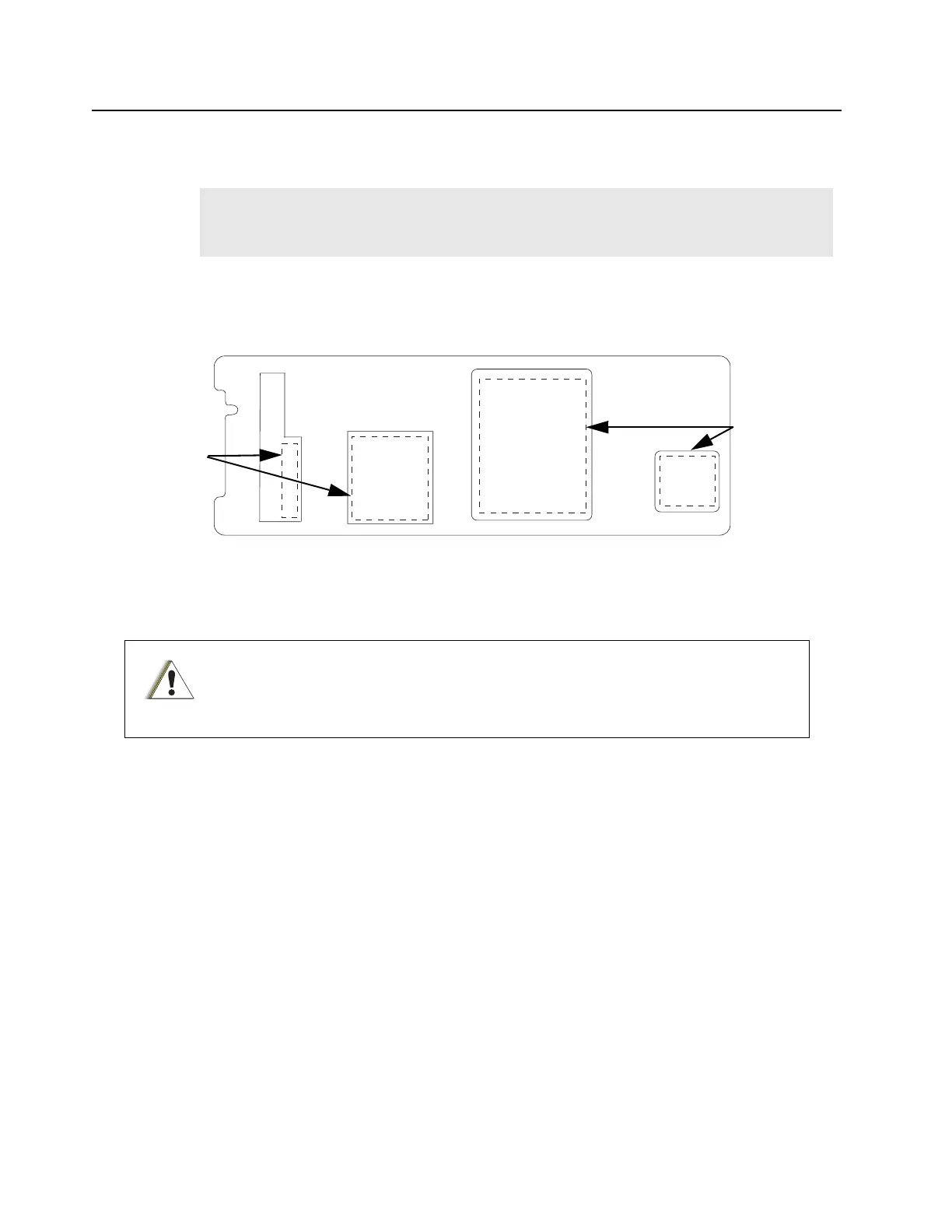
To reapply thermal grease on the PA metal casting when reassembling the Output and RF Board,
refer to Figure 3-5.
Figure 3-5 Areas to apply thermal grease on the PA metal casting
3.3.2.1 Output Board
3.3.2.1.1 Disassembly
1. Remove the 5 screws (M3.5, Tx15) from the board using a Torque driver.
2. Unsolder the output connector from the board.
3. Unsolder the lead which connects the board to the Circulator.
4. Unsolder the 2 omega straps on the output board, which connect it to the distribution
board.
3.3.2.1.2 Reassembly
1. Apply thermal grease to the marked section on the reverse side of the replacement
output board as shown in Figure 3-6.
2. On the metal casting, remove the old thermal grease, and apply the new grease on the
four outline areas as shown in Figure 3-5.
3. Install the replacement output board.
4. Secure the board with the 5 screws (M3.5, Tx15 at 15 in-lbs) according to the order
Note
The Distribution Board omega straps and the Circulator leads overlap onto the RF Board
and Output Board, and should be the first to be removed and the last to be replaced if
either the RF Board or Output Board requires removal/replacement.
The PA will require recalibration if the Output Board is replaced. Recalibration is not
necessary if the RF Board is replaced. If recalibration is not possible but is required,
the PA module will need to be replaced.
Thermal
Compound
Outline Marking
Thermal
Compound
Outline Marking
C a u t i o n
 Loading...


