1-10 Basic Troubleshooting
In addition to providing power to the noted FRU and controllers, the PS also provides the
following:
- AC Failure detect signaling to the SCM
- Output over-current protection for all three outputs
- Self contained cooling fan and control circuit (thermal shut down if the environmental
temperatures exceed the cooling capacity provided by the fan).
• Further details can be found in the individual “Theory of Operation” sections of the respective
FRU chapters in the MOTOTRBO
TM
MTR3000 Base Station/Repeater Basic Service Manual
(68007024096).
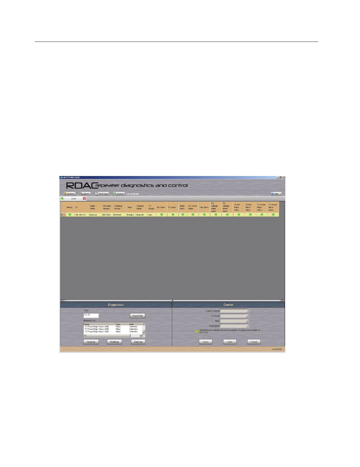
1.5 Basic Troubleshooting
Diagnostic tests are available for the SCM, Exciter, PA, and Receiver Modules. If a problem occurs
during station operation, it is logged as an alarm that is read with the Repeater Diagnostic and
Control application (RDAC). Refer to Figure 1-4 for the RDAC’s diagnostic screen.
Figure 1-4. RDAC’s Diagnostic Screen
The station operator can then evaluate the problem locally or remotely, as the station will maintain an
Alarm Log with the name of the alarm that has failed since the last power up. Via the RDAC
application’s Alarm Log, the alarm messages will aid in identifying the FRU that failed along with the
fault condition.
After booting up the base station/repeater, the 6 LEDs (Power/Status, Tx Slot 1, Tx Slot 2, Rx Slot 1,
Rx Slot 2 and the Mode LEDs) flashes in unison.
 Loading...


