Basic Troubleshooting 1-11
The general status and condition of the MTR3000 base station/repeater can be obtained by
observing the eight LED indicators on the front panel. Table 1-5 shows the LED symbols and their
meaning, while Table 1-6 identifies the information conveyed via the LED indicators. Table 1-7 shows
the alarm diagnosis table and probable diagnosis to aid in identifying the fault.
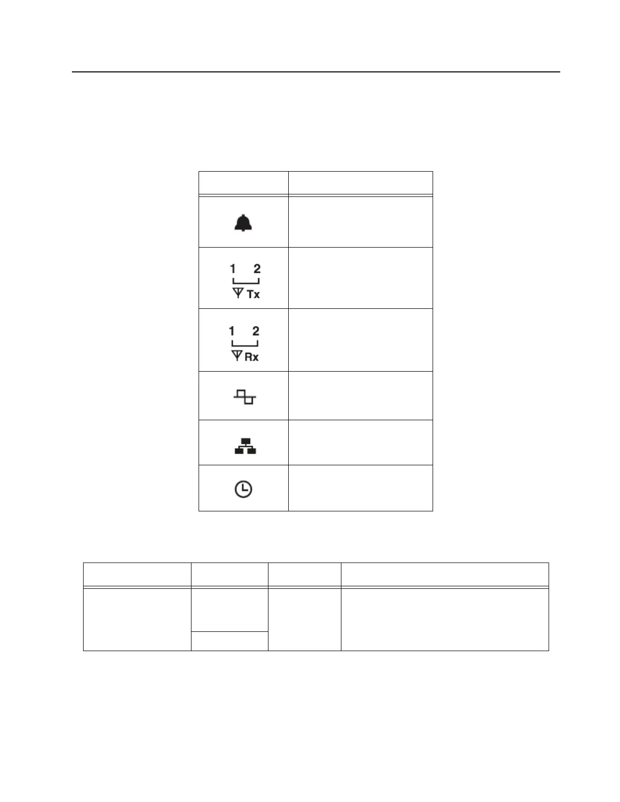
Table 1-5. Front Panel LED indicators
LED
Definition
Status
Tx Slot 1 (for label number 1)
Tx Slot 2 (for label number 2)
Rx Slot 1 (for label number 1)
Rx Slot 2 (for label number 2)
Mode
Ethernet Link
Reference
Table 1-6. MTR3000 Software and Hardware Controlled LEDs
LED Function Name LED Color LED State Status Indication
Power/Status, Tx Slot 1,
Tx Slot 2, Rx Slot 1, Rx
Slot 2
Mode
Amber
Flashing Station booting up
Blue
 Loading...


