4-18 Theory of Operation
4.2.11 Front Panel (FP) Connectors and Switch
Table 4-10 to Table 4-15 describe the front panel connectors and switch.
Figure 4-8 describes the USB connector pin-out.
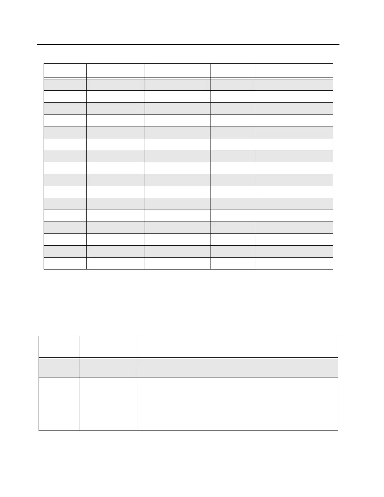
A15 Ground Ground
B1 ABA_RX Abacus SSI Data 3.3 V Rx OMAP McBSP2.DR
B2 ABA_FS Abacus SSI FS 3.3 V Rx OMAP McBSP2.FSR
B3 Ground Ground
B4 ABA_PD Abacus SPI MOSI 3.3 V FPGA
B5 ABA_DOUTB Abacus SPI MISO 3.3 V FPGA
B6 NC No Connect on Controller
B7 RX_CPLD_CLK CPLD SPI CLK 3.3 V FPGA
B8 RX_CPLD_MOSI CPLD SPI MOSI 3.3 V FPGA
B9 RX_CPLD_ADD_2 CPLD SPI Address 2 3.3 V FPGA
B10 Ground Ground
B11 NC No Connect on Controller
B12 +8V Rx 8.0 V supply 8.0 V 8VDC
B13 +14_2V Rx 14.2 V supply 14.2 V 14.2VDC
B14 Ground Ground
B15 CLK_RX_16_8MHZ Station Reference 3.3 V Clock Buffer
Table 4-10 SCM FP Connectors
Connector
Name
Connector Type Purpose
USB Service
(J3009M7)
USB Type B Service Computer connection. This connector is accessible with front cover in
place.VBUS (+5 V) is not provided on the USB connector.
Mic
(J3000M7)
RJ45 (8 Pin) Microphone connection. Compatible with microphone GMN6147 (older model)
or GMMN4063. This connector is accessible with front cover in place.
Note : The Mic port is only supported in analog mode regardless of the Mic
used. For older model of microphone (GMN6147), the 3 control buttons for
speaker volume control, Rx monitor and Intercom control functions are not
supported.
Table 4-9 MTR3000 Controller Receiver Connector connection (Continued)
Pin Signal Name Description Signal Level Controller Connection
 Loading...


