Theory of Operation 4-21
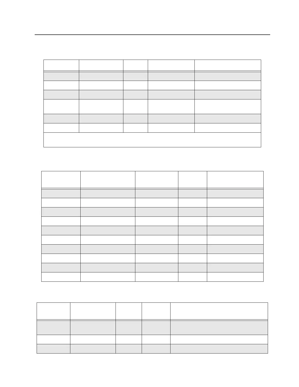
Table 4-13 SCM FP Speaker Connector Pin-out
Pin Number Pin Name I/O Voltage Level (V) Pin Description
1 GND GND GND Ground
2 14.2V 14.2V 14.2 V 14.2 V supplied to the speaker
3 GND GND GND Ground
4 SPEAKER_AUDIO Output 1.4 Vpp Audio Output. Level indicated
here is the maximum value
G1 GND GND GND Ground
G2 GND GND GND Ground
From the base station/repeater front view, the SPEAKER connector pin 1 to pin 4 are arranged from left to
right sequentially.
Table 4-14 SCM FP Ethernet Connector Pin-out
Pin Number Pin Name I/O
Voltage
Level
Pin Description
1 ENET_TXN_FP Output 5 V Ethernet Tx negative
2 ENET_TXN_FP Output 5 V Ethernet Tx positive
3 ENET_RXN_FP Input 5 V Ethernet Rx negative
4 GND GND GND Ground
5 GND GND GND Ground
6 ENET_RXP_FP Input 5 V Ethernet Rx positive
7 GND GND GND Ground
8 GND GND GND Ground
G1 GND GND GND Ground
G2 GND GND GND Ground
Table 4-15 SCM FP External Reference Connector Pin-out
Pin Number Pin Name I/O
Voltage
Level
Pin Description
C EXT_REFERENCE Input 5 V 5 MHz or 10 MHz external reference. This can
be either a sine or a square wave.
G1 GND GND GND Ground
G2 GND GND GND Ground
 Loading...


