4-16 Theory of Operation
4.2.8 Backplane
The connector that connects the controller to the backplane is a right angle, 96-Pin Connector. It
provides connectivity between the MTR3000 controller and other station FRU, such as the Wireline
card, the AUXIO card as well as, third party equipment. For details on backplane connection, refer to
MTR3000 Backplane chapter in the MOTOTRBO
TM
MTR3000 Base Station/Repeater Basic Service
Manual (68007024096).
4.2.9 Exciter
The connector (J3600M3) used to connect the controller to the Exciter is a dual row, right angle,
early entry receptacle, without flange, 30-Pin Connector. It provides 16.8 MHz reference clock,
14.2 V, 10 V and 8 V supply voltage, SPI, Trident SSI and other digital handshake signals with the
Exciter.
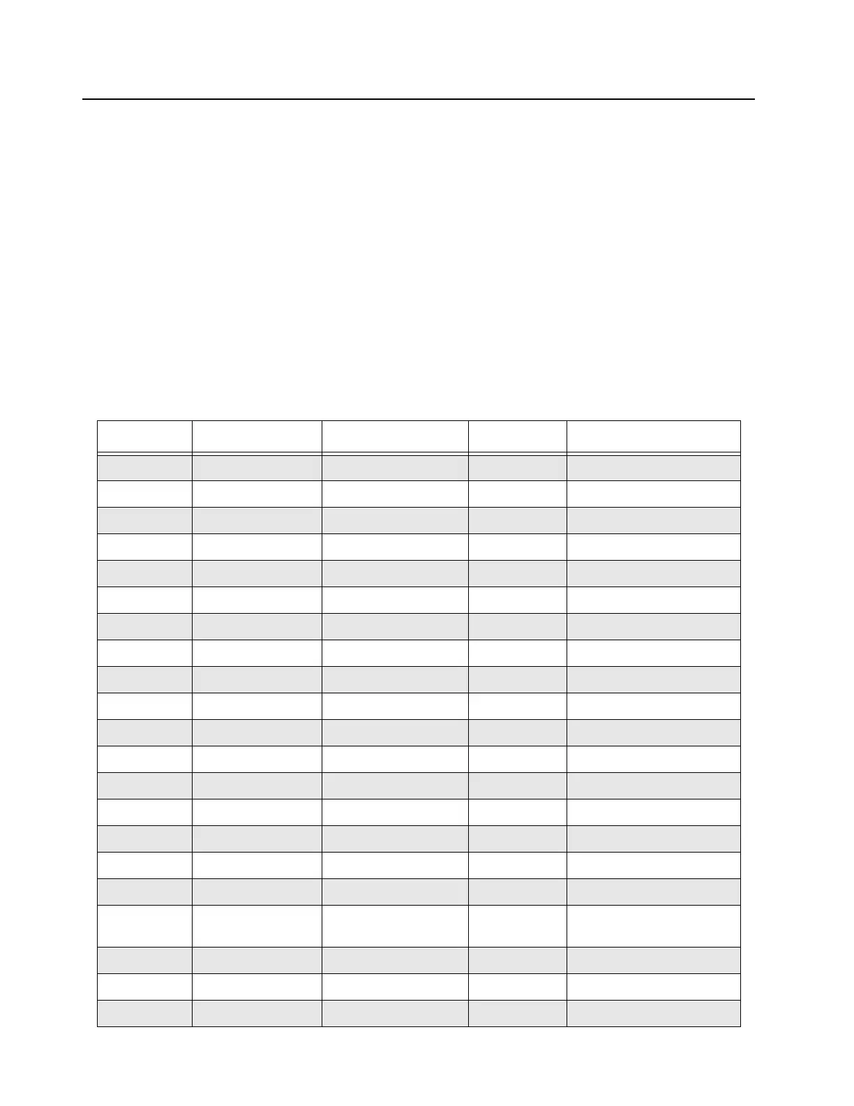
Refer to Table 4-8 for pinout for the Exciter connector.
Table 4-8 MTR3000 Controller Exciter Connector connection
Pin Signal Name Description Signal Level Controller Connection
A1 Ground Ground
A2 Ground Ground
A3 TXD_EX Trident SSI data 2.775 V Tx OMAP McBSP2.DX
A4 TXFS_EX Trident SSI frame sync 2.775 V Tx OMAP McBSP2.FSX
A5 Ground Ground
A6 EX_ENABLE_EX Ex Slot Enable 3.3 V Tx OMAP GPIO28
A7 NC No Connect on Controller
A8 NC No Connect on Controller
A9 +8V Ex 8.0 V supply 8 V 8VDC
A10 Ground Ground
A11 EX_CPLD_ADD_0 CPLD SPI address 0 3.3 V FPGA
A12 Ground Ground
A13 EX_CPLD_CLK CPLD SPI input clock 3.3 V Clock Buffer
A14 EX_CPLD_CE CPLD SPI chip enable 3.3 V Ground
A15 NC No connect on Controller
B1 CLK_EX_16_8MHZ Station Reference 3.3 V Clock Buffer
B2 Ground Ground
B3 DMCS_EX Trident SSI data
enable
2.775 V Tx OMAP GPIO2
B4 TXCLK_EX Trident SSI data clock 2.775 V Tx OMAP McBSP2.SCK
B5 Ground Ground
B6 NC No Connect on Controller
 Loading...


