Theory of Operation 4-13
4.2.6 Audio
There are four transmit inputs: Tx Audio, Tx Audio-Pre and Tx Data on the backplane DB25
connector, and the Microphone input on a front panel RJ45 connector.
Tx Audio is a flat (not pre-emphasized) input which is used if the incoming transmit audio signal is
already pre-emphasized, if hardware pre-emphasis is not needed, or if the CPS has pre-emphasis
enabled. The Tx Audio-Pre input provides a hardware pre-emphasis filter. The Tx Data input is used
for low speed data, Private-Line (PL) and Digital Private Line (DPL) signals. The microphone input
can be selected under software control to be flat or pre-emphasized using an OMAP GPIO.
The Tx Audio, Tx Audio-Pre and microphone inputs pass through a hardware modulation limiter and
splatter filter before being summed with Tx Data, which bypasses the limiter and splatter filter. Mic is
never summed with TDATA. This summed signal is applied to the MAKO codec “mic” input. The
audio signal without Tx Data is provided on the MAKO codec “aux_mic” input. The MAKO codec
“aux_mic” is used for microphone audio only.
There are three receive outputs: Rx Audio and Aux Rx Audio on the backplane DB25 connector and
speaker audio on a front panel RJ11.
The speaker audio is the sum of the MAKO codec output (demodulated audio) and transmit audio.
The speaker audio can be selected under software control to be flat or pre-emphasized using an
OMAP GPIO. A high pass filter removes any data, PL or DPL from the speaker audio. A
programmable attenuator is used to adjust the speaker audio level before being output on the RJ11
connector.
Aux Rx Audio is the output of the MAKO codec (demodulated audio), and Rx Audio is the sum of the
MAKO codec output and microphone audio.
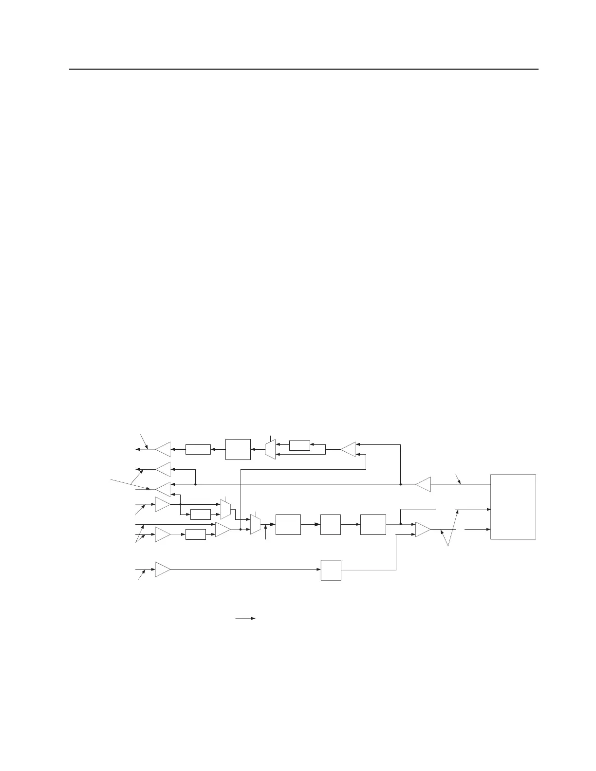
Refer to Figure 4-6 for audio paths and voltage levels.
Figure 4-6 Station Control Module (SCM) Audio Path
+
Rx Audio
Mic
+ +
Limiter
1.0 Vpp
Max
MPUIO0
Splatter
filter
Aux Mic
Mic
In
Spe
aker Out
(to amplified speaker)
80 mVrms
226 mVpp
Attn
330 mVrms
933 mVpp
(into 50K Ohms)
56 mVrms
158 mVpp
0 to 500mVrms
0 to 1.4 Vpp
Nominal levels for 60% FSD with
1KHz tone
Hig
h
Pass
Filter
I2C Audio
Attenuator
0
1
MPUIO13
+
De-
Emphasis
Pr
e-
Emphasis
0
1
0
1
Pre-
Emphasis
MPUIO10
Aux Rx Audio
VC_OUT
AUX_MIC
MIC
MAKO
CODEC
Default Path selected
221 mVrms
600 mVpp
Attn
80 mVrms Voice
16mVrms data
74 mVrms
209 mVpp
Tx Data/PL/DPL
80 mVrms
226 mVpp
Tx Audio -
Pre
Tx Audio -
Fla
t
 Loading...


