Theory of Operation 4-9
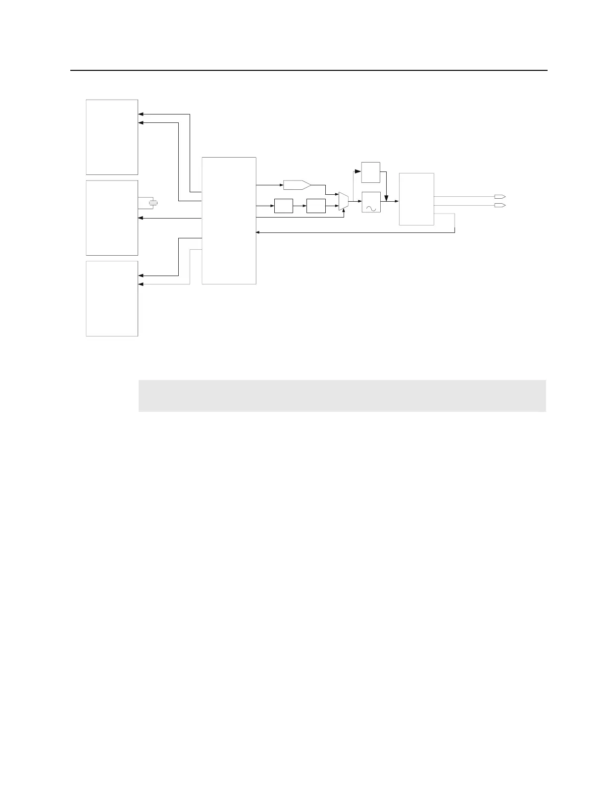
Refer to Figure 4-3 for the MTR3000 Controller Clock Configuration.
Figure 4-3 MTR3000 Controller Clock Configuration
4.2.4 MAKO
MAKO IC (U1402M1) is a customized IC and the SCM uses this device to leverage some unique
functionality that it provides.
Most of the MAKO functionality are not used on the SCM. Only the MAKO codec, USB driver, ADC,
DAC, and some voltage regulators are used for MTR3000 base station/repeater. The 9 channel
general purpose ADC is used for various controller metering.
Refer to Figure 4-4 for the MAKO block diagram and usage of MTR3000 Controller.
Note
For the OCXO kit, the controller must be warmed up for a minimum of 15 minutes before the
base station/repeater is enabled for transmit.
Y0
Charge
Pump
Loop
Filter
16.8MHz
Y1
CLK_RX_16_8MHZ
J3601 – B15
Y2
CLK_EX_16_8MHZ
J3600 – B1
CLKIN
FPGA
MAKO
OSC_IN
CLK32K_IN
OSC_IN
CLK32K_IN
RXOMAP_12MHZ
RXOMAP_32.768KHZ
TXOMAP_32.768KHZ
TXOMAP_12MHZ
XTAL32_IN
TCXO_IN
MAKO_32.768KHZ
MAKO_24.576MHZ
XTAL32_OUT
TXOMAP
U1000M1
Y1400M1
U1402M1
RXOMAP
U1001M1
U2000M5
DAC
U2401M5
Mux
U2403M5
16.8MHz
OCXO
Y2401M5
16.8MHz
TCXO
Y2400M5
CLOCK
BUFFER
U2402M5
Note: OCXO (Y2401M5) will be placed for CLN8565 kits only.
 Loading...


