3-1
Chapter 3 MTR3000 Power Amplifier
3.1 Overview
This section provides an overview, detailed Theory of Operation and troubleshooting information for
the Power Amplifier (PA) Module. The block diagrams, schematic diagrams, overlays, and parts lists
are provided on foldout sheets. Each block diagram shows the location and reference designation
for all electrical components. A complete list of all parts is provided with the parts ordered according
to the schematic reference number.
For specifications of the PA, refer to the MOTOTRBO
TM
MTR3000 Base Station/Repeater Basic
Service Manual (68007024096).
3.2 Theory of Operation
The following theory of operation describes the operation of the Power Amplifier circuitry at a
detailed level. The information is presented to give the service technician an understanding of the
functions performed by the module in order to facilitate maintenance and troubleshooting to the
component level.
The Power Amplifier (PA) module is designed for continuous-duty operation across its specified
frequency band and transmit power range. It is a multi-stage RF amplifier, and contains various
metering, control, and protection circuitry that govern its operation. The PA module will accept a
fixed-level RF input signal from the Exciter module, and amplify it to the desired transmit power and
deliver it to the PA output connector, which is the Base Station/Repeater (BR) antenna port. Through
a combination of software (SW) and hardware (HW) controls, the PA transmit power is determined.
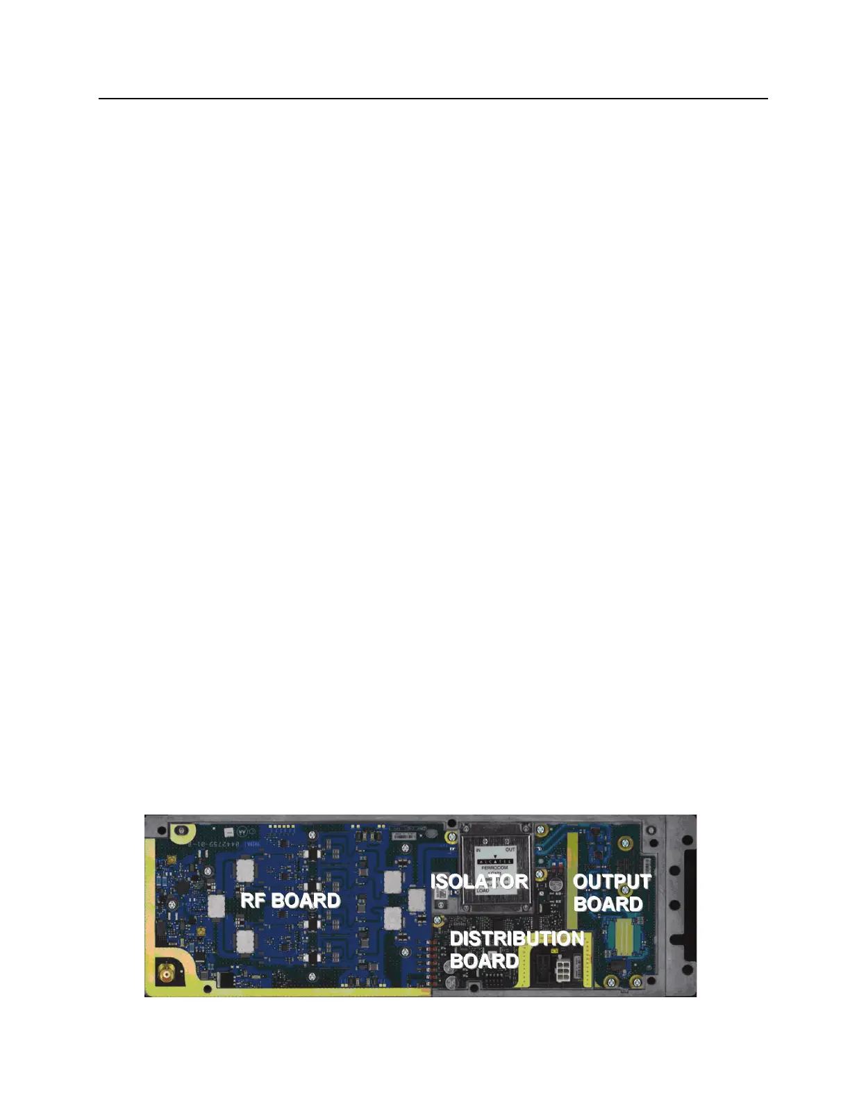
The PA module contains the sub-modules below:
• RF Board (replaceable)
• Output Board (replaceable)
• Distribution Board (replaceable)
• Internal isolator (replaceable) which consists of a Circulator and isolation load.
Refer to Figure 3-1 for the PA sub-modules.
Figure 3-1 PA sub-modules
 Loading...


