3-4 Theory of Operation
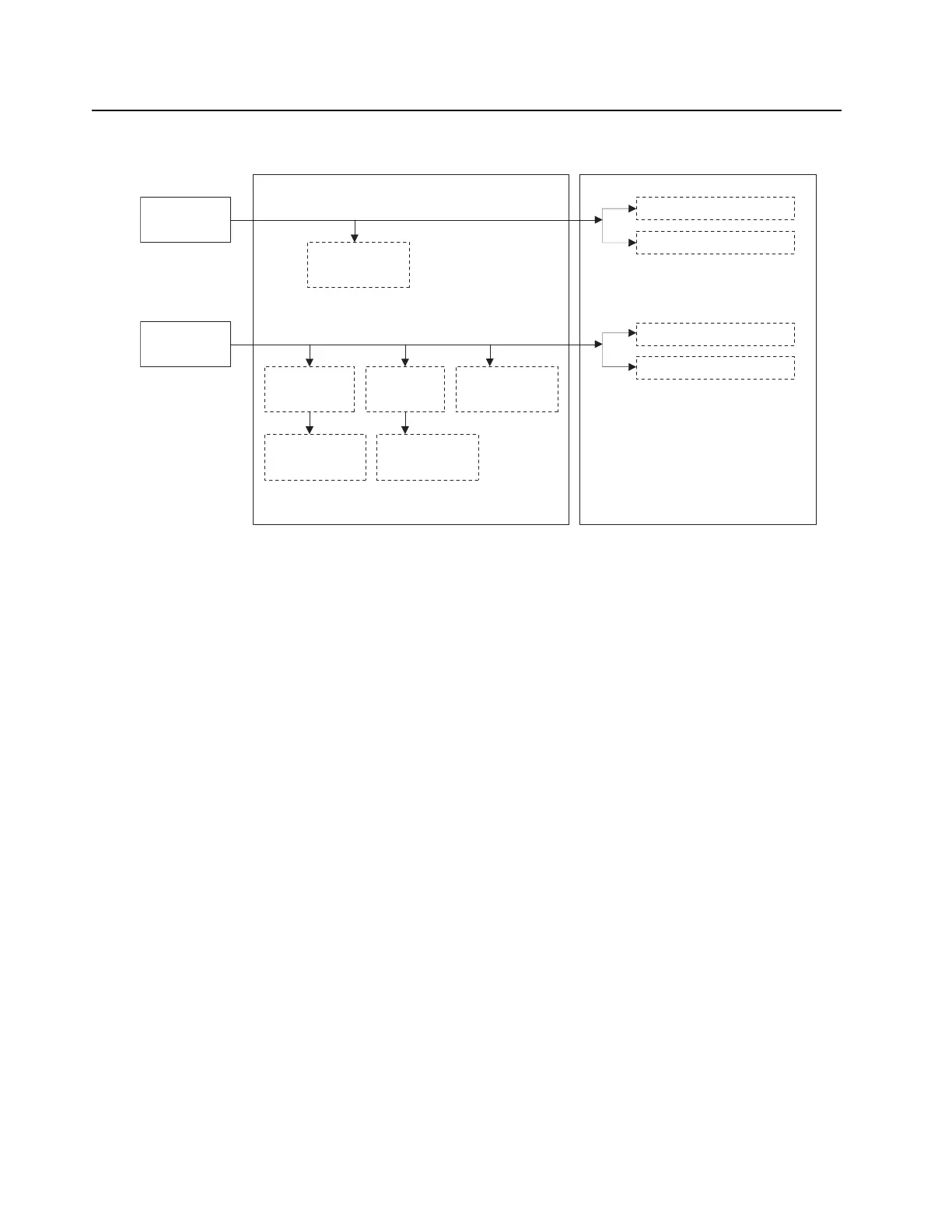
Figure 3-3 PA DC Power Structure
PA DC Load Definitions:
• Load A – Metering Circuit
• Load B – Final Amplifier RF Devices
• Load C – Driver Amplifier RF Devices
• Load D – SPI, Metering, Power Control
• Load E – SPI, Metering, Power Control
• Load F – Metering, Power Control, PA Fan
• Load G – Final Amplifier Bias Circuitry
• Load H – Driver Amplifier Bias Circuitry, Driver Amplifier RF Device
3.2.1 RF Board
The RF Board is a replaceable module within the PA, and contains the driver and final amplifier
circuits, as well as the PA input BNC connector. This board performs all of the RF amplification
within the PA required to achieve the desired transmit power. The output power of the RF Board is
greater than the PA output power, as it must overcome the losses introduced by the elements
following the RF board within the PA, such as the isolator and harmonic filter.
The RF board utilizes local heat spreaders under the main RF amplifier devices and final amplifier
combiner isolation loads. These heat spreaders contact the PA cast heat sink and provide a thermal
path to maintain adequate operational temperatures of these components. Thermal grease is used
between the heat spreader and the PA cast heat sink interface to maintain a proper thermal
interface.
28.6V Input
from PS
14.2V Input
from PS
Driver Amplifier (Load H)
Final Amplifier (Load G)
Distribution
Board (Load A)
5V Linear
Regulator
3.3V Linear
Regulator
Distribution
Board (Load F)
Dis
tribution
Board (Load D)
Distribution Board
Driver Amplifier (Load C)
Final Amplifier (Load B)
RF Board
Distribution
Board (Load E)
 Loading...


