Theory of Operation 3-3
controlled, and requires no SW interaction for this to occur. Additionally, the PA also contains
metering circuitry to monitor for low output power and fan failure alarming, although these are
informational in nature and do not result in a HW or SW action on the PA.
The PA can be placed in standby mode when not transmitting. This is achieved through the
PA_Enable signal controlled by the SCM through the PA signal connector. When this signal is in the
high state, the PA is enabled. When the PA is placed in standby mode, the power consumption of
the PA is significantly reduced.
The PA HW type is identified by way of the PA_IDA and PA_IDB meters within the PA. These signals
are provided to the A/D, and are also controlled by the D/A to result in multiple states for each A/D
input. These meter values are used to determine HW type.
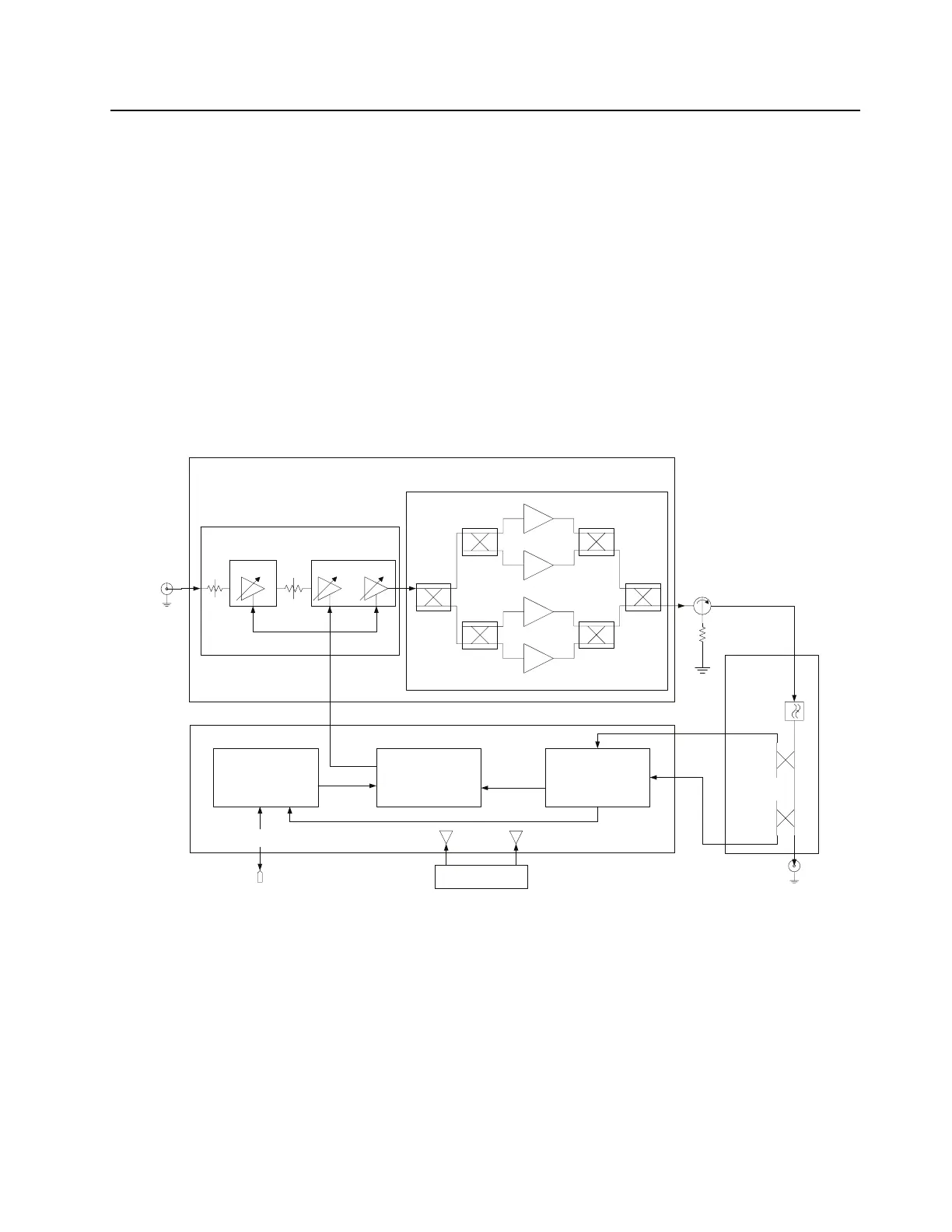
Refer to Figure 3-2 for the functional block diagram of the PA and Figure 3-3 for the PA DC Power
Structure.
Figure 3-2 PA Functional Block Diagram
DC Distribution Board
Power Control
Circuitry
RF Board
Output
Board
Driver Amplifier
Q2100 Q2300
Final Amplifier
Q4300
Q4400
Q4600
Q4500
RF Input
Connector
U4110
U4120
U4130
U4920
U4930
U4910
Forward
Power
Detector
Harmonic
Filter
Circulator
Reverse
Power
Detector
50 Ohm
Load
RF Output
Connector
Backplane
Connector
(10 Pin)
SPI Circuitry
- CPLD
-DAC
- ADC
- NVM
SPI
Buss
Metering
Circuitry
Power
Control
Voltage
28.6V
Buss
14.2V
Buss
Power Supply
Connector
 Loading...


