Theory of Operation 4-15
• Supports one 10BT port with automatic polarity detection and correction
• Supports full and half duplex mode and flow control
• Universal Serial Bus (USB) and Joint Test Action Group (JTAG) parameters
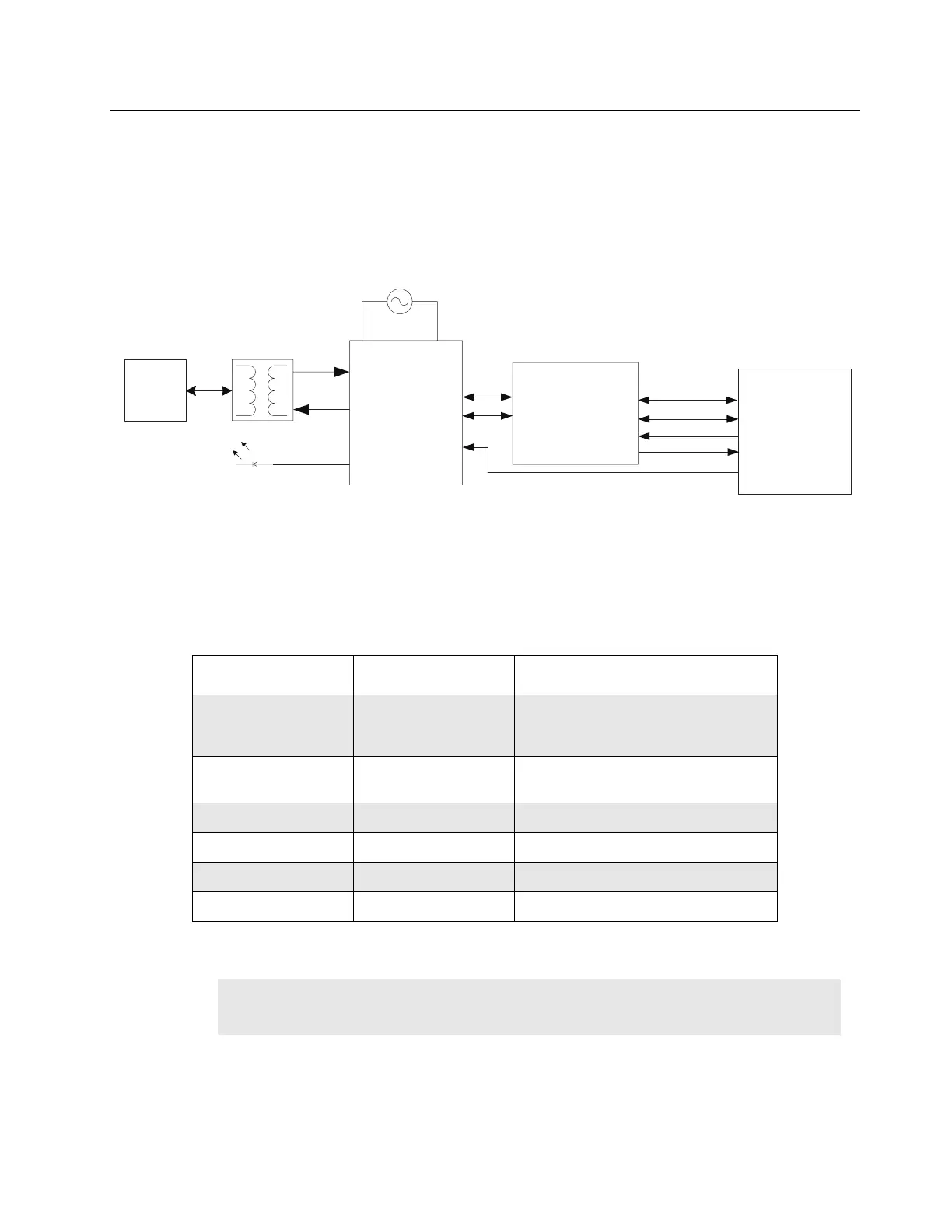
Refer to Figure 4-7 for the MTR3000 Ethernet bridge IC connection.
Figure 4-7 MTR3000 Controller Ethernet Connection
4.2.7.3 LAN9500i Power-up Configuration
SMSC LAN9500i will be configured into the following mode after power-up.
Table 4-7 SMSC LAN9500i Default Configuration after Power-up
Pin Name Default Setting Description
EEP_SIZE PU 1 = 256/512 byte EEPROM is attached
and a total of nine address bits are
used.
1, 2
PORT_SWAP PD 0 = USBDP maps to the USB D+ line
and USBDM maps to the USB D- line.
1
RMT_WKP PD 0 = Remote wakeup is not supported.
1
EEP_DISABLE PD 0 = EEPROM is recognized if present.
1
AUTOMDIX_EN PU 1 = Auto-MDIX is enabled.
1
PWR_SEL PD 0 = The LAN9500i is bus powered.
Note 1. Internal PU and PD are used, no external connections.
2. No external EEPROM is connected.
LAN9500i
USBDM
25MHz Oscillator
TXP
TXN
RJ45
NLNKA
TXOMAP
USB2_TXEN
USB2_DAT
USB2_SE0
ARMIO15
GREEN
USBDP
VBUS_DET
MAKO
USB2DM
USB2DP
USB2_OE
USB2_DAT
USB2_SE0
GPIO38
USB_INTX
 Loading...


