4-20 Theory of Operation
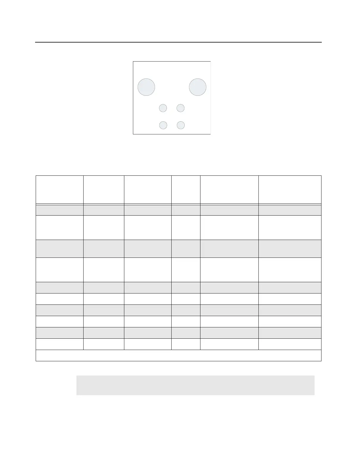
Figure 4-8 USB connector pin-out
Table 4-12 SCM FP Microphone Connector Pin-out
MIC
Connector Pin
Number
Schematic
Pin Number
Pin Name I/O Voltage Level Pin Description
1 5 NC NC NC No Connect
2 4 Reserved Input Reserved for future
use. DO NOT
CONNECT
3 6 MIC_PTT* Input 0 to 5 V Voltage generated by
PTT button
4 3 MIC_AUDIO Input 850 mVpp Audio Input, Level
indicated here is the
maximum value
5 7 GND GND GND Ground
6 2 NC NC NC No Connect
7 8 NC NC NC No Connect
8 1 NC NC NC No Connect
G1 G1 GND GND GND Ground
G2 G2 GND GND GND Ground
From the base station/repeater front view, the MIC connector pin 1 to pin 8 are arranged from right to left sequentially.
Note The schematic pin number and MIC pin number does not match due to imprecise
geometry and this will remain, since it is widely used in many other kits within Motorola.
4 3
1 2
G1 G2
USB TYPE B
CONNECTOR
(BOTTOM VIEW)
 Loading...


