Troubleshooting 3-11
shown in Figure 3-6.
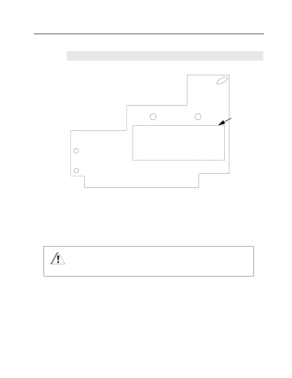
Figure 3-6 Sequence to tighten back screws on the output board
5. Solder the 2 omega straps, which connect the output board to the distribution board.
6. Solder the lead that connects the board to the Circulator.
7. Solder the output connector to the board.
3.3.2.2 Distribution Board
3.3.2.2.1 Disassembly
1. Remove the 2 screws (M3.5, Tx15) from the board using a Torque driver.
2. Unsolder the lead which connects the fan connector to the board.
3. Unsolder the 2 omega straps on the output board, which connect the distribution board
to the output board.
4. Unsolder the 7 omega straps on the RF board, which connect the distribution board to
the RF board.
3.3.2.2.2 Reassembly
Note
Ensure that the output board is placed under the Circulator lead.
The PA will require recalibration if the Distribution Board is replaced. Recalibration is
not necessary if the RF Board is replaced. If recalibration is not possible but is
required, the PA module will need to be replaced.
4
1
2
5
3
Thermal
Compound
Outline Marking
C a u t i o n
 Loading...


