3-12 Troubleshooting
1. Install the replacement distribution board.
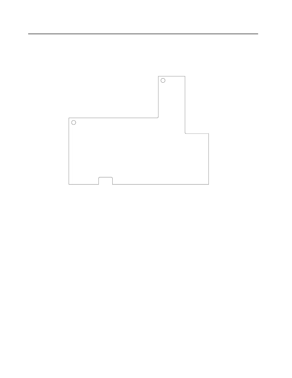
2. Secure the board with the 2 screws (M3.5, Tx15 at 15 in-lbs) according to the order
shown in Figure 3-7.
Figure 3-7 Sequence to tighten back screws on the distribution board
3. Solder the 7 omega straps, which connect the board to the RF board.
4. Solder the 2 omega straps, which connect the board to the output board.
5. Solder the lead that connects the board to the fan connector.
3.3.2.3 RF board
3.3.2.3.1 Disassembly
1. Remove the 8 screws (M3.5, Tx15) from the board using a Torque driver.
2. Unsolder the Circulator from the board.
3. Unsolder the 7 omega straps on the RF board, which connect it to the distribution board.
4. Disassemble the Circulator and the load resistor according to the procedures outlined at
Section 3.3.2.4.1 and Section 3.3.2.5.1.
5. Gently lift the RF board to remove it. Some additional force may be needed to overcome
the thermal grease bonds under the board
.
2
1
 Loading...


