Troubleshooting 3-13
3.3.2.3.2 Reassembly
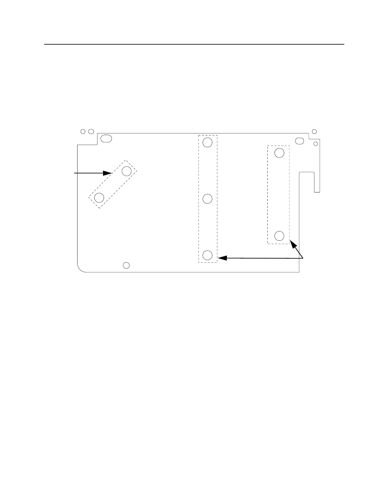
1. Apply thermal grease to the three coins (driver coin, final device coin, final combiner
coin) on the reverse side of the replacement RF board as shown in Figure 3-8.
2. On the metal casting, remove the old thermal grease, and apply the new grease on the
four outline areas as shown in Figure 3-5.
3. Install the replacement RF board.
4. Secure the board with the 8 screws (M3.5, Tx15 at 15 in-lbs) according to the order
shown in Figure 3-8.
Figure 3-8 Sequence to tighten back screws on the RF board
5. Solder the 7 omega straps, which connect the board to the distribution board.
6. Solder the lead that connects the board to the Circulator.
7. Reassemble the Circulator and the load resistor according to the procedures outlined at
Section 3.3.2.4.2 and Section 3.3.2.5.2.
3.3.2.4 Circulator
3.3.2.4.1 Disassembly
1. Remove the 4 screws (M3, Tx10) from the Circulator using a Torque driver.
2. Unsolder the Circulator from the RF board.
3. Unsolder the Circulator from the output board.
4. Unsolder the Circulator from the load resistor.
3.3.2.4.2 Reassembly
1. On the replacement Circulator, apply thermal grease to the underside of the Circulator
as well as the Circulator pocket on the metal casting.
2. Install the replacement Circulator.
3. Secure the Circulator with the 4 screws (M3, Tx10 at 10 in-lbs) which was previously
1
2
3
4
5
6
7
8
Thermal
Compound
Outline Marking
Thermal
Compound
Outline
Marking
 Loading...


