NE-4100 Series User’s Manual Serial Command Mode
9-8
Serial Command Mode
OP Code Parameter Comments
ES
0: disable
1: enable HW trigger
2: enable SW trigger
enable serial command mode
EC
three ASCII characters in hex
code (i.e., “A1A2A3” for ASCII
characters 0xA1, 0xA2, 0xA3)
SW trigger characters
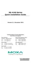
Operation Flow Chart
Check Serial
Command
Mode Trigger
Normal
Serial-to-Ethernet
Function
Poll DIO 0
Status
Check Serial
Port Data
Enter Serial
Command
Process Command
Exit Serial Command Mode
and Restart
DIO 0 Low
(HW Trigger On)
3-characte
ATTENTION
This flowchart represents a continual process. You can start trace out a logical flow by starting
anywhere on the chart.
Diamonds represent decision points. Only one path leading out of any diamond can be followed.

 Loading...