TN-5516/5518 User’s Manual Featured Functions
3-58
After proper configuration:
y Packets from Device A will travel through Trunk Port 3 with tagged VID 5. Switch B will
recognize its VLAN, pass it to port 6, and then remove tags received successfully by Device G,
and vice versa.
y Packets from Devices B and C will travel through Trunk Port 3 with tagged VID 2. Switch B
recognizes its VLAN, passes it to port 4, and then removes tags received successfully by
Device F, and vice versa.
y Packets from Device D will travel through Trunk Port 3 with tagged VID 3. Switch B will
recognize its VLAN, pass to port 5, and then remove tags received successfully by Device H.
Packets from Device H will travel through Trunk Port 3 with PVID 3. Switch A will
recognize its VLAN and pass it to port 2, but will not remove tags received successfully by
Device D.
y Packets from Device E will travel through Trunk Port 3 with tagged VID 4. Switch B will
recognize its VLAN, pass it to port 7, and then remove tags received successfully by Device I.
Packets from Device I will travel through Trunk Port 3 with tagged VID 4. Switch A will
recognize its VLAN and pass it to port 2, but will not remove tags received successfully by
Device E.
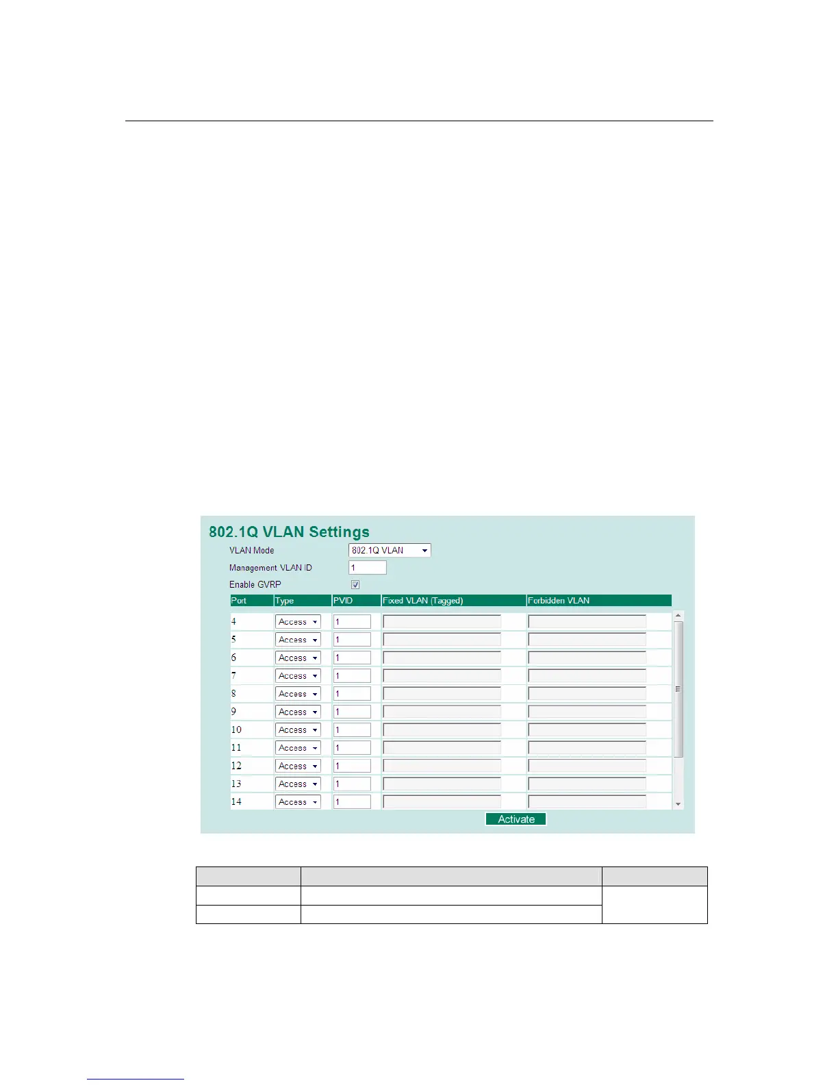
Configuring Virtual LAN
VLAN Settings
To configure 802.1Q VLAN on the TN-5500, use the VLAN Setting page to configure the ports.
VLAN Mode
Setting Description Factory Default
802.1Q VLAN Set VLAN mode to 802.1Q VLAN
Port-based VLAN Set VLAN mode to Port-based VLAN
802.1Q VLAN
 Loading...