SUPREMATouch
148
Installation
MSA
US
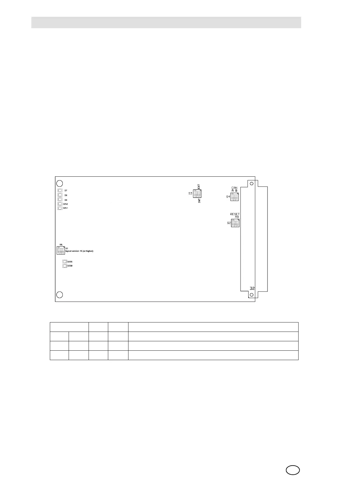
Configuration of the MGO-20 Module
The operating mode for the input signal through the CAN-A or CAN-B bus as well as the switch-
on and configuration properties are to be set with DIL switches S3 and S4. Switch S1 is omitted.
Figures 78 show the switch positions on the printed circuit board.
The module MGO-20 is furnished with a bootloader for installing new firmware. The switch S2-1
= OFF activates the bootloader mode.
NOTE: The normal function of the module is deactivated in the bootloader mode. This mode
should therefore be used only by the MSA service personnel!
Configuration of turn-on and failure behaviour of the MGO module is effected via the
DIL switch on the MIB module (FREE A + FREE B).
Fig. 78 MGO Module, as from layout version 15
As of layout version 12, for SIL applications, the operating modes for control via CAN-A or
CAN-B buses, the turn-on behaviour must be configured with the S3 and S4 DIL switches.
CAN-A BR11 + BR13 = CLOSED & BR12 + BR14 = OPEN (Standard Setting)
CAN-B BR11 + BR13 = OPEN & BR12 + BR14 = CLOSED
Switch S2 Function
1234
ON ON OFF OFF Factory setting/Do not change
OFF X X X Bootloader active (only MGO-20)