SUPREMATouch
208
Installation
MSA
US
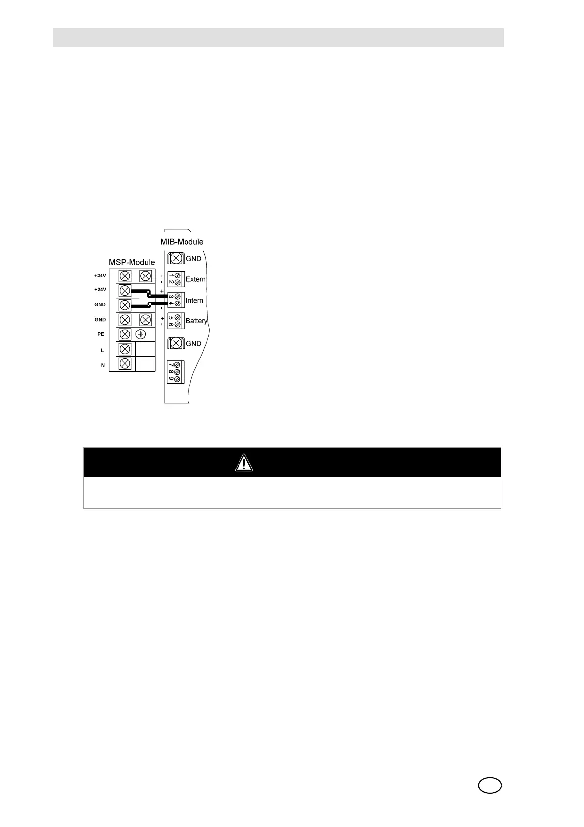
Fig. 150 MSP Module, Terminal Assignment
Fig. 151 Connection diagram of the MSP Module
As shown in Figure 151, the +24 V output terminal of the MSP module must be connected to the
+ve terminal of the INT connection, and the GND output terminal of the MSP module must be con-
nected to the -ve terminal of the INT connection of the MIB module.
The line power is supplied via the terminals “L” and “N” of the MSP module.
NOTE: Do not supply line power to the MIB module. This will damage the SUPREMA system.
The ground wire is connected to the PE terminal of the MSP module.
NOTE: Before turning on the line voltage during the start-up procedure, reinstall the Plexiglas cov-
er over the connection terminals of the MSP module in order to prevent any danger that might
arise from accidental contact with the line voltage.
10.12 Labelling Concept
Labelling fields are provided on the various modules for the numbering of the plug-in modules, the
connector plugs, and connected inputs and outputs. The customer is free to mark them in any way
deemed fit except the MPI and MCI modules that are an exception due to the lack of space. In the
following, the labelling fields and a possible plan for marking them is presented. This plan is mere-
Power Supply Unit - Terminal Designation Function
+ 24 V + S Output: +24 VDC Sense Connection
+ 24 V Output: +24 VDC
GND Output: GND
GND - S Output: GND Sense Connection
PE Ground Wire Connection
LLine
N Neutral
CAUTION
Connection of the line power must be made with the power switched off and all relevant safety
regulations should be complied with.