SUPREMA
228
Connection of Peripherals
MSA
US
reset manually (status no longer exists). The current status of the sampling point with the data
structure shown in Figure 166: Protocol printer, Data Structure is printed out along with the date
and time of the most recent change of status.
NOTE: This formatting can be changed by the user!
12.3 Bus Connection
To connect the SUPREMA system to existing industrial control systems, it is necessary to com-
municate with other data buses for processing of measuring values, alarms/failures.
The signal conversion necessary is realised by SUPREMA gateways.
NOTE: 2 gateways per CAN channel can be connected.
NOTE: The gateways are not included in the approval!
For the time being, the following bus systems are supported:
- Modbus RTU Standard
- Modbus TCP, Description of function - see Software Manual "SUPREMA Gateway CAN/
Modbus TCP with SUPREMA-CANopen Firmware"
- Profibus DP
ATTENTION: Modbus can only be used for data collection or record keeping with regards to com-
bustible gas detection and not for performance verification.
Further data bus systems on request.
SUPREMA Gateway CAN/Modbus RTU (PKV30)
(Not contained in EC-type examination certificate DMT 03 ATEX G 003 X)
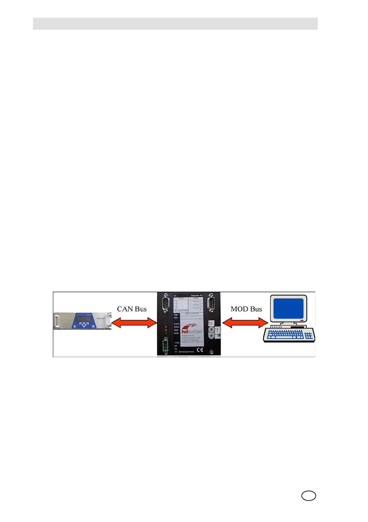
Fig. 167 Connection the SUPREMA to external systems using a Modbus RTU gateway
The gateway is installed on a mounting rail in the cabinet and requires a 24 V dc supply voltage
(X1). The SUPREMA transfers the data via the CAN bus which is connected to X2 at the gateway.
For data supply to the Modbus, there are 3 physically different serial interfaces (X3) and 3 different
data formats to be selected.
The gateway generally operates as a slave for the CAN bus and Modbus. The SUPREMA and the
control system must therefore initiate the gateway to send data.
Enclosed with the gateway are the following 5 manuals for installation, parameters and operation: