SUPREMA
260
SUPREMA Sensor Data Sheets
MSA
US
15 SUPREMA Sensor Data Sheets
The individual sensor connections are illustrated below. For active sensors, the input current sig-
nal is monitored, so that each failure is detected and reported by the SUPREMA system.
There are also lists containing details of the operating current, power requirement of the sensors,
the maximum allowable cable lengths (maximum allowable cable resistance) and the screening.
For further information on the sensors, please see the Operating and Maintenance Instructions for
the individual sensor types.
NOTE: Only at use of the MCI module with part no. 10043997 and 10044020 meets the require-
ments according to EN 60079-29-1 for active sensors at 3-wire operation.
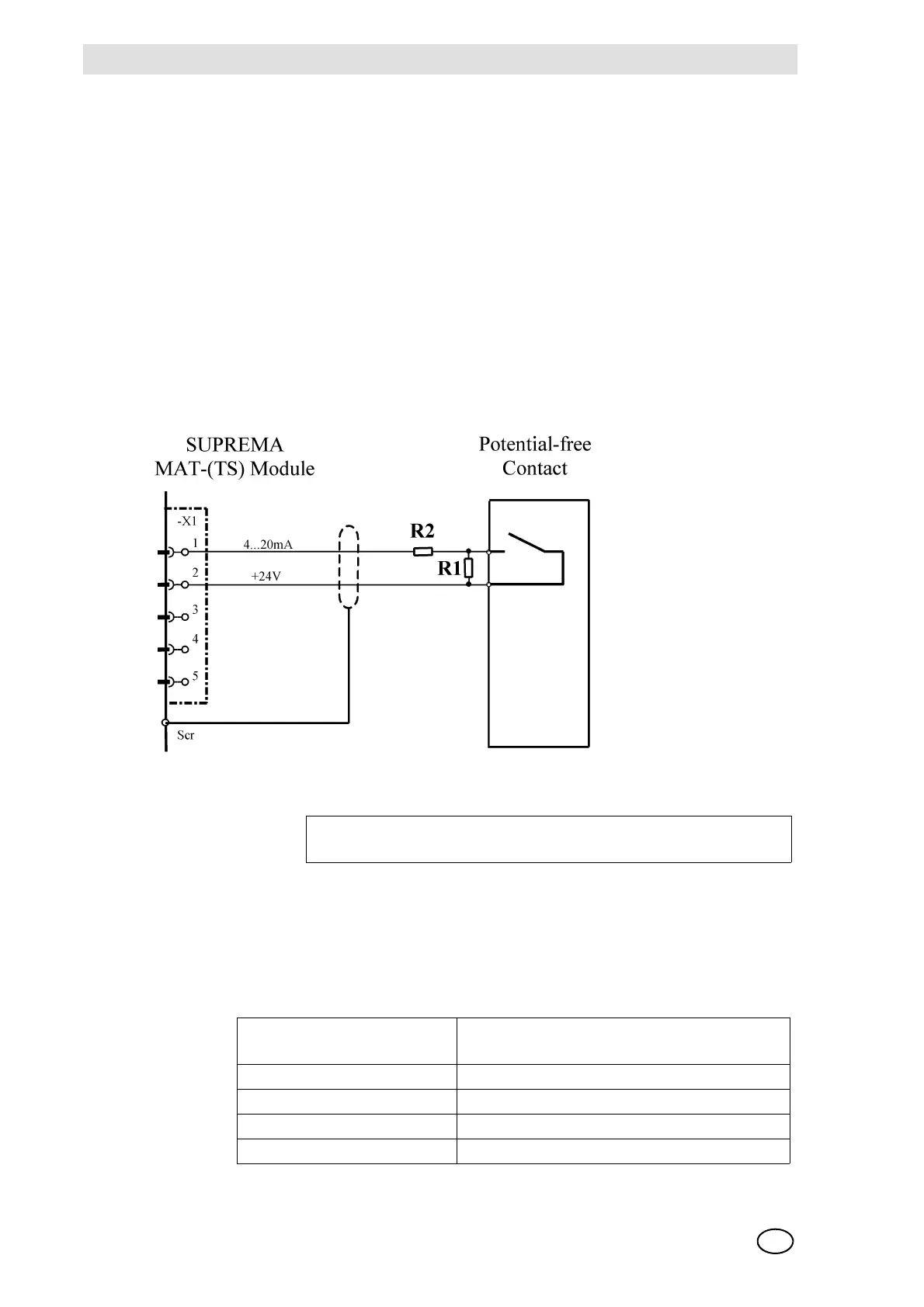
15.1 SUPREMA Sensor Data Sheet Contact
Connection.: potential-free contact
Fig. 180 Connection scheme Contact
Connection module: MCI (BR101 and BR102 open) Standard configuration
(passive/2-wire/4 ... 20 mA/current supply)
Sensor
simulation module: 4 ... 20mA (Order No.: 10030262)
Ohms resistors to generate an input current: R1 = 2.7 kΩ (0.5 W)
R2 = 1.8 kΩ (0.5 W)
Connection
data:
Cable type signal 2-core, 80 % screened
Maximum cable length 1000 m (at 1.5 mm
2
cross section per wire)
Cable diameter 8 ... 12 mm
Cross section per wire allowed 0.75 ... 2.5 mm
2
Min. contact closure time 2 seconds