SUPREMATouch
160
Installation
MSA
US
Fig. 87 Slots and Positions on the rack
Slots in the Rack
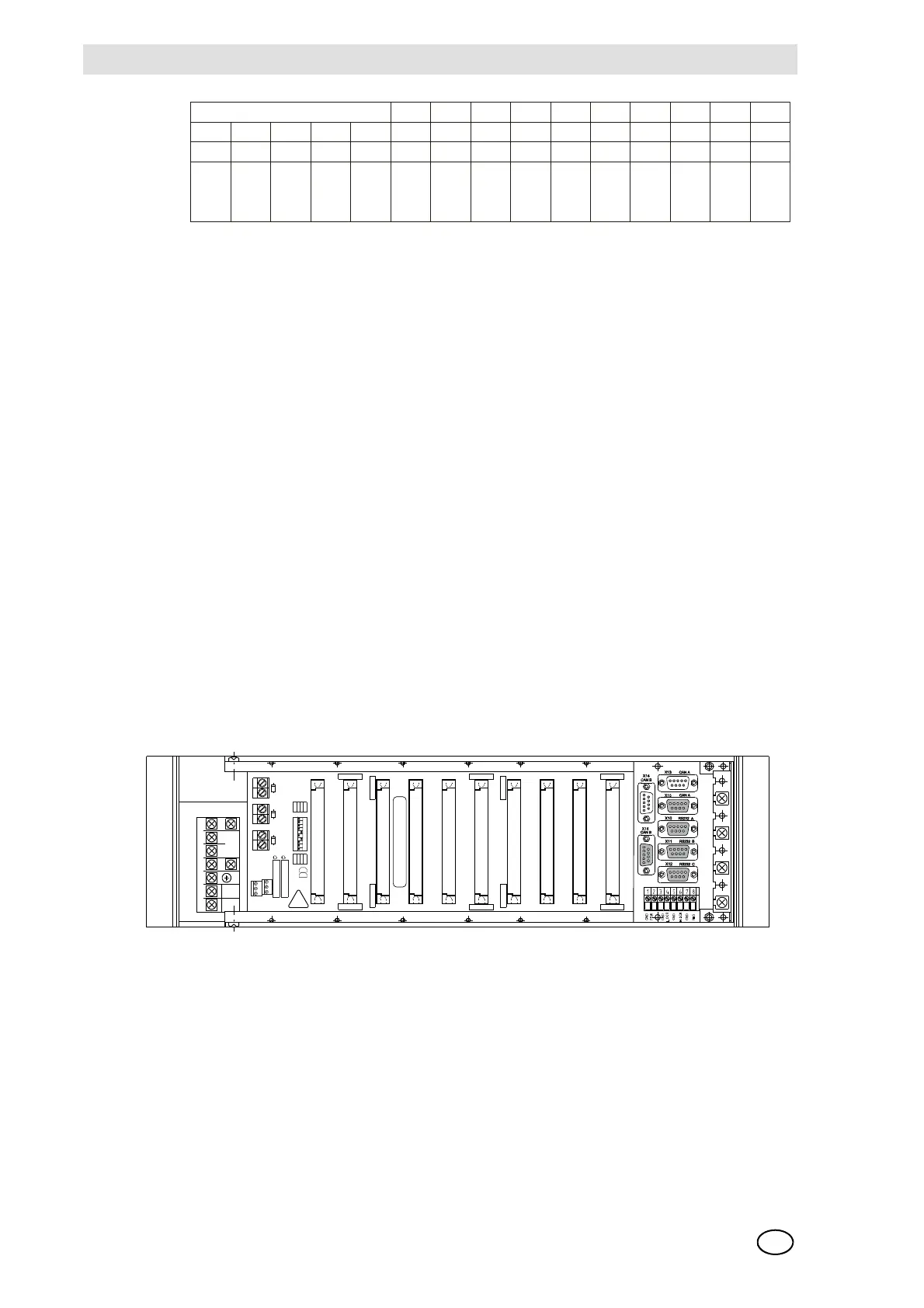
Connection sites on the rear of the rack:
Fig. 88 Rear of the Rack
System Requirements
The following requirements must be fulfilled in order to build a functional system:
Exactly one MCP module, one MDC module and one MDO module are required for a system (up
to 8 racks) (non-redundant design). The MDC module must be properly connected by ribbon cable
to the MDO module mounted in the front panel.
Exactly one MDA module is required for a rack (non-redundant design) if MAI modules are also
present in the rack.
Slots 1-3: slots for MCP and/or MDC modules only
Slots 4-5: slots for MDA modules only
Slots 6-13: slots for INPUT/OUTPUT modules
Slots 14-15: slots for INPUT/OUTPUT (but no MAI) modules only
INPUT: MAI modules (with MPI/MCI modules)
MBC modules
OUTPUT: MGO module
MAO module
MBC module
MST: connection site for the MST module only
(Positions 1-10): connection site for:
- MAT module (8 x 5 terminals)
- MUT module (40-way ribbon cable)
- MRO 8 module (Position 9!)
10
Pos.
4
Slot
9
Pos.
3
Slot
8
Pos.
2
Slot
7
Pos.
1
Slot
6
Slot
1
Slot
2
Slot
3
Slot
4
Slot
5
MAI
MAO
MGO
MBC
MAI
MAO
MGO
MBC
MAI
MAO
MGO
MBC
MAI
MAO
MGO
MBC
MDC
MCP
MDC
MCP
MDC
MCP
MDA MDA
Rear:
Front:
EXT
INT
BAT
+
-
X21
+
-
+
-
X22X23
POS 10
POS 9
POS 8
POS 7
POS 6
POS 5
POS 4
POS 3
POS 2
POS 1
1
2
3
4
5
6
SYSTEM POWER MSP 10
N L PE GND GND +24V +24V
RL2
RL1
ON
7
89
10
11 1 2
110