Installation
SUPREMATouch
169
US
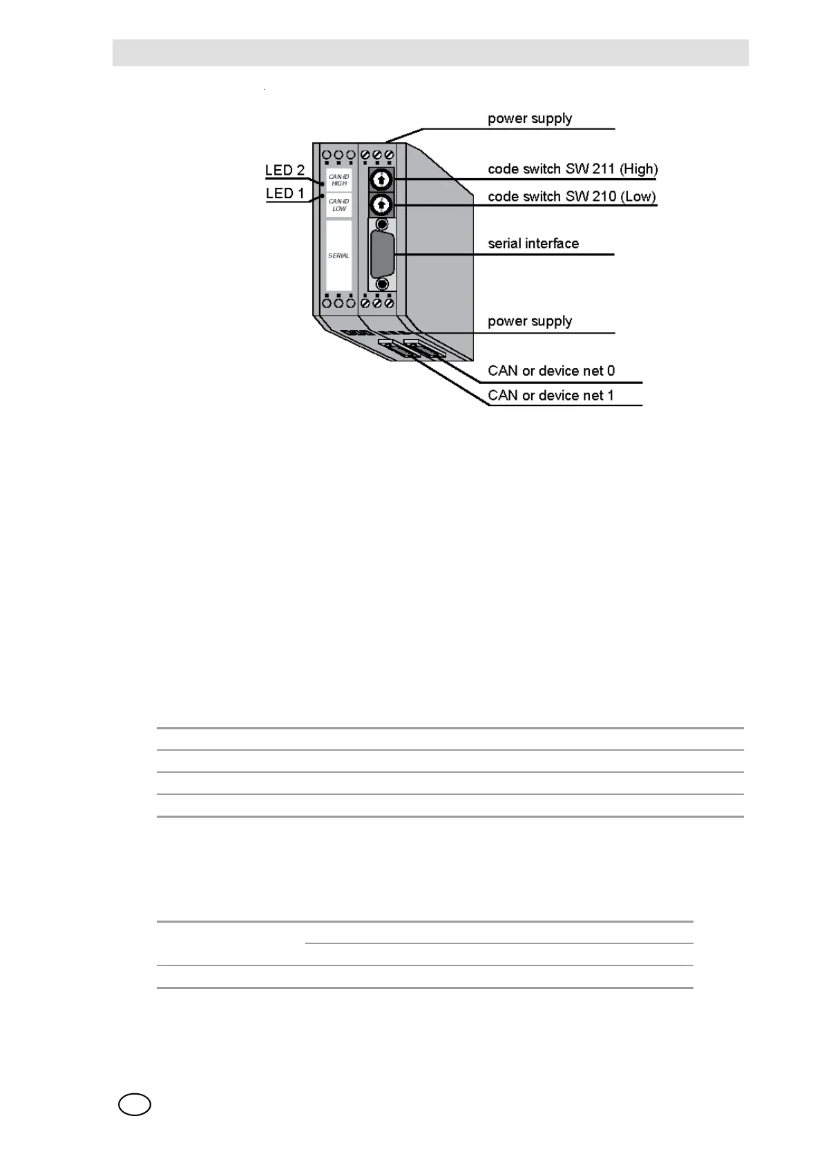
Fig. 106 SUPREMA CAN-Bridge CBM
The SUPREMA CAN BRIDGE is supplied with 24V DC (X101). The CAN Bus of the Basic Rack
is connected to NET 0 (X400), and the satellite rack is connected to NET1 (X400) (Exact connec-
tion assignments are to be seen from the CAN Bridge hardware manual).
For parameter setting, a serial interface (DSUB plug connector X100) is provided. The CAN
Bridge parameters can be set using a terminal program (e.g. Hyper Terminal for Windows).Details
of this process are described below.
The code switches SW211 and SW210 of the CAN Bridge are only for internal service purposes
and must always be in position 0. When both LED‘s (1 and 2) are on the status is ‘good‘. If there
is a failure at one of the two CAN buses, the corresponding LED will flash, LED 1 for NET 1, and
LED 2 for NET 0.
For the correct function of the SUPREMA CAN bridge, some points must be considered:
NOTE: 32 filters max. may be set, i.e., in a satellite, 9 MGO/MAO modules max. can be integrated.
The number of MDA/MAI modules per rack is not limited.
As to a):
Fig. 107 Baudrate at the Central Rack
a) Baudrate setting at the Central Rack (depends on the number of measuring points)
b) Baudrate setting at the satellite rack (depends on the distance of the satellite)
c) Rack number (Dip switch at the MIB module)
d) Components of the Satellite racks (Plug positions of the MDA, MGO, MAO, MAI modules)
Measuring points Bit rate setting in kB/s Bridge
Simplex/Duplex Command
1 - 256 250 B0:4