SUPREMATouch
180
Installation
MSA
US
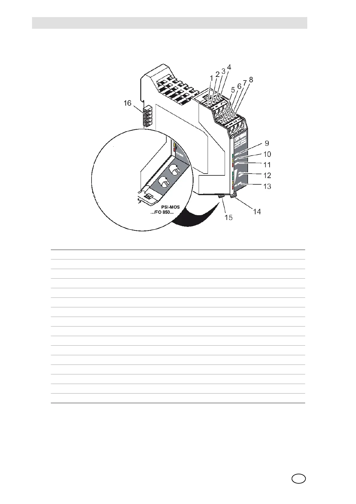
View of the terminals/LEDs:
Fig. 115 LWL converter terminals/LEDs
1. Voltage supply: 24 VDC
2. Voltage supply: 0 VDC
3. Connection switching contact (onlybase module)
4. Connection switching contact (onlybase module)
5. CAN connection: Shield (onlybase module)
6. CAN connection: GND (onlybase module)
7. CAN connection: C_High (onlybase module)
8. CAN connection: C_Low (onlybase module)
9. LED: Ready for operation/Redundancy-Standby operation
10. LED: Bus activity
11. LED: Bus error
12. LED field: Qualitiy of LWL Signal
13. LED: LWL error
14. LWL connection: Sending path
15. LWL connection: Receive path
16. Backplane