XON Digital Plat
orm
User Manual
Revision A
3
2019 MST Global Commercial in Confidence
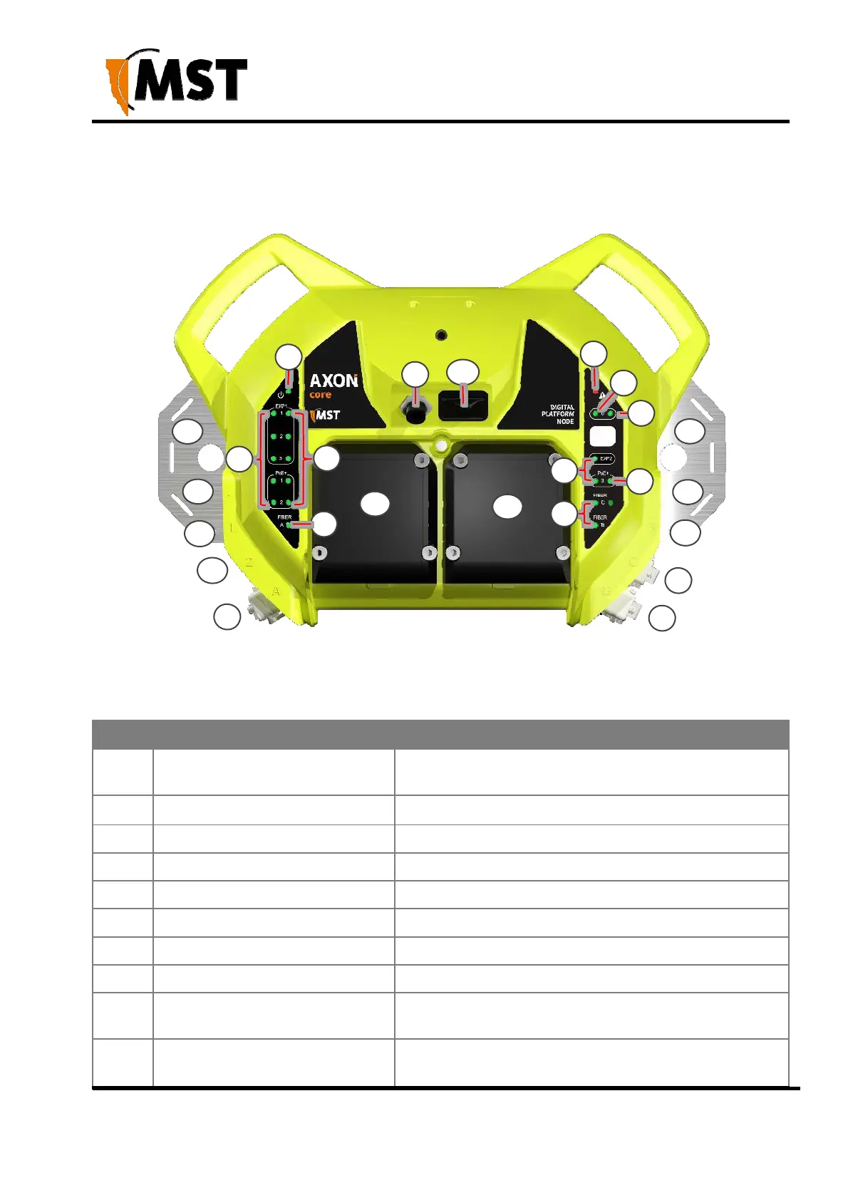
2.1 Hardware Overview
The features and functions of AXON Core are illustrated in Figure 2: AXON Core layout and the
accompanying table.
2
3
9
15
8
7
13 13
4
5
5
4
11
12
10
6
10
14
14
6
10
1
1
1
Figure 2: AXON Core layout
Key Description Function
1
Composite (fibre + power) cable
port
Connector for data transmission and / or DC power
distribution. There are three ports: A, B and C
2
Power and Status LED Power and Status LED
3 Power warning LED Power warning LED
4 PoE+ port status dual colour LEDsPoE+ port status dual colour LEDs
5 PoE+ port activity LEDs PoE+ port activity LEDs
6 Fibre port status LEDs Fibre port status LEDs
7 Radio port status LED Radio port status LED
8 Radio port activity LED Radio port activity LED
9 PoE+ AXON Air port
PoE+ port typically used by AXON Air module. It can
also be used for other purposes
10 PoE+ Ethernet ports
External Ethernet port with IEEE 802.3at PoE+ supply
capability for powering client devices.