9
2019 MST Global Commercial in Confidence
XON Digital Plat
orm
User Manual
Revision A
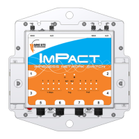
7 Downstream PoE LED Downstream PoE activity LED
8 Upstream PoE LED Upstream PoE activity LED
9 Tracking activity LED Tracking activity LED
10 External Antenna External 2.5dB, omnidirectional antenna
11
ntenna swivel mounting area Mounting area used to accommodate optional
antenna swivel mechanism (sold separately).
12 Mounting holes Two mounting holes on the top of the module
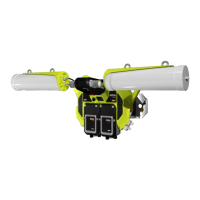
3.3 Daisy Chaining of AXON Air units
Each AXON Air features a two-port Ethernet switch, which enables daisy chaining of individual AXON
Air units via a CAT5 cable. The maximum distance in between AXON Air nodes in such scenario is
100 meters. A maximum of three AXON Air units can be daisy chained together.
The unit gets its power from one of its upstream PoE port and passes it through to the next access
point in the chain via the downstream port. AXON Air negotiates a PoE+ Class 4 power requirement,
whilst drawing 4W nominally.
The AXON Air operational parameters can be configured through its own web browser interface or via
the centralised configuration management. For more information, see Chapter 7: Configuration Using
the Web Interface