XON Digital Plat
orm
User Manual
Revision A
4
2019 MST Global Commercial in Confidence
11 Factory defaults button
Factory reset button for the unit. Pressing it for 5…15
seconds will cause factory reset
12 Reset button (RED) Pressing this button will cause switch core reset without
losing the device configuration.
13 Mounting holes Rear mounting bracket with holes for mounting AXON
Core on the wall or roof.
14 Covered Expansion Socket Expansion socket covered with a protective cover.
15 SD card Inserting a card from another switch and power cycling
XON Core will install switch configuration stored on the
card
2.3
Connectivity
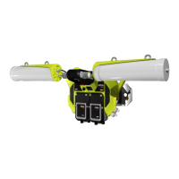
AXON Core has three types of network connections:
Composite Fibre Ports
Ethernet Ports
Expansion interfaces
2.3.1 Composite Fibre Ports
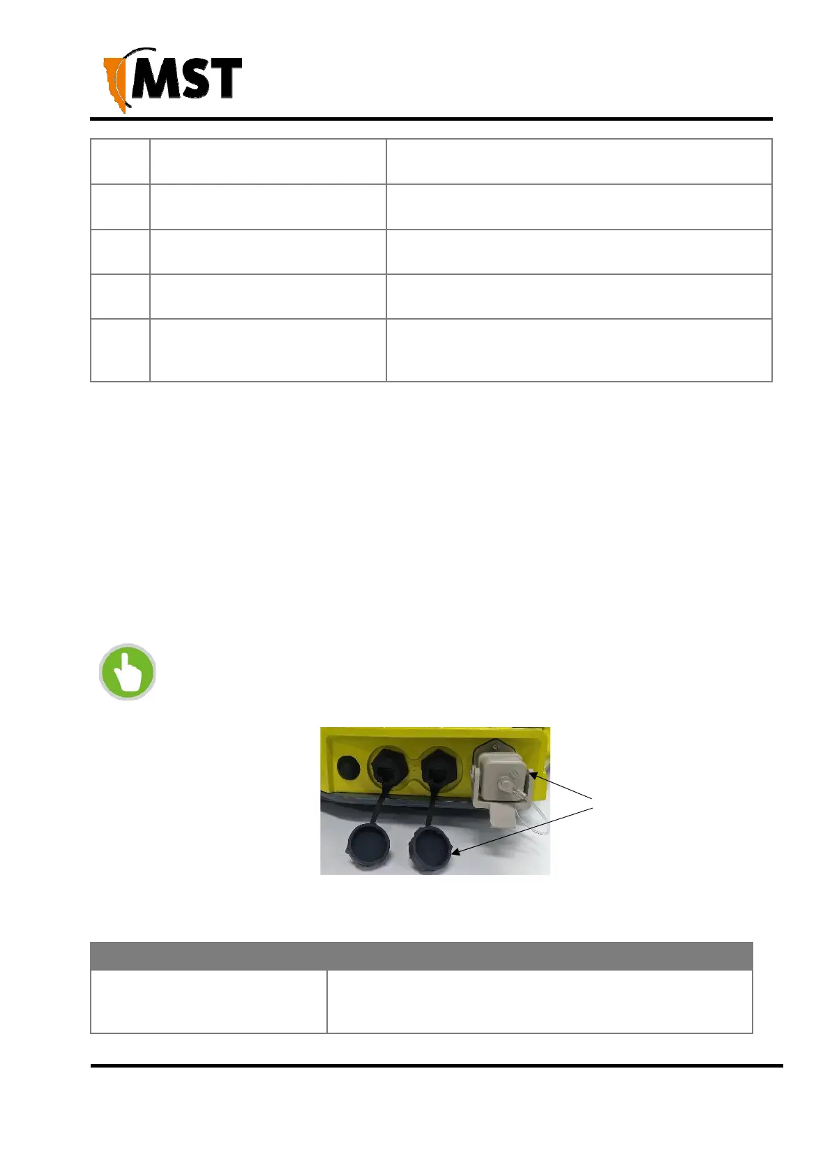
AXON Core unit has three composite fibre port connectors with a crush protection cover. Each
connector consists of two electrical contacts and a duplex LC single mode optic fibre (SMOF)
receptacle as shown in Figure 3: Composite fibre ports.
NOTE: A protective cover or a mating cable connector must be attached to unused
ports to maintain the IP65 (Ingress Protection) rating of the unit
Protective covers
Figure 3: Composite fibre ports
Each port can be connected in one of the following ways:
Port connection Description
DC power only connection
DC power cable to connect the PSU to the electrical
contacts on an AXON Core. By convention, this cable is
connected to port A.