XON Digital Plat
orm
User Manual
Revision A
5
2019 MST Global Commercial in Confidence
Fibre only connection
fibre optic cable terminated to the fibre contacts of the AXON
Core composite connector.
Fibre and DC power connection
composite cable providing fibre optic connectivity and power
to AXON Core.
Fibre optic cabling provides numerous benefits over Ethernet cabling, with superior signal integrity
and no signal interference from high-powered electronics. It also enables units to be spaced over
longer distances without the distance limitation of Ethernet cabling.
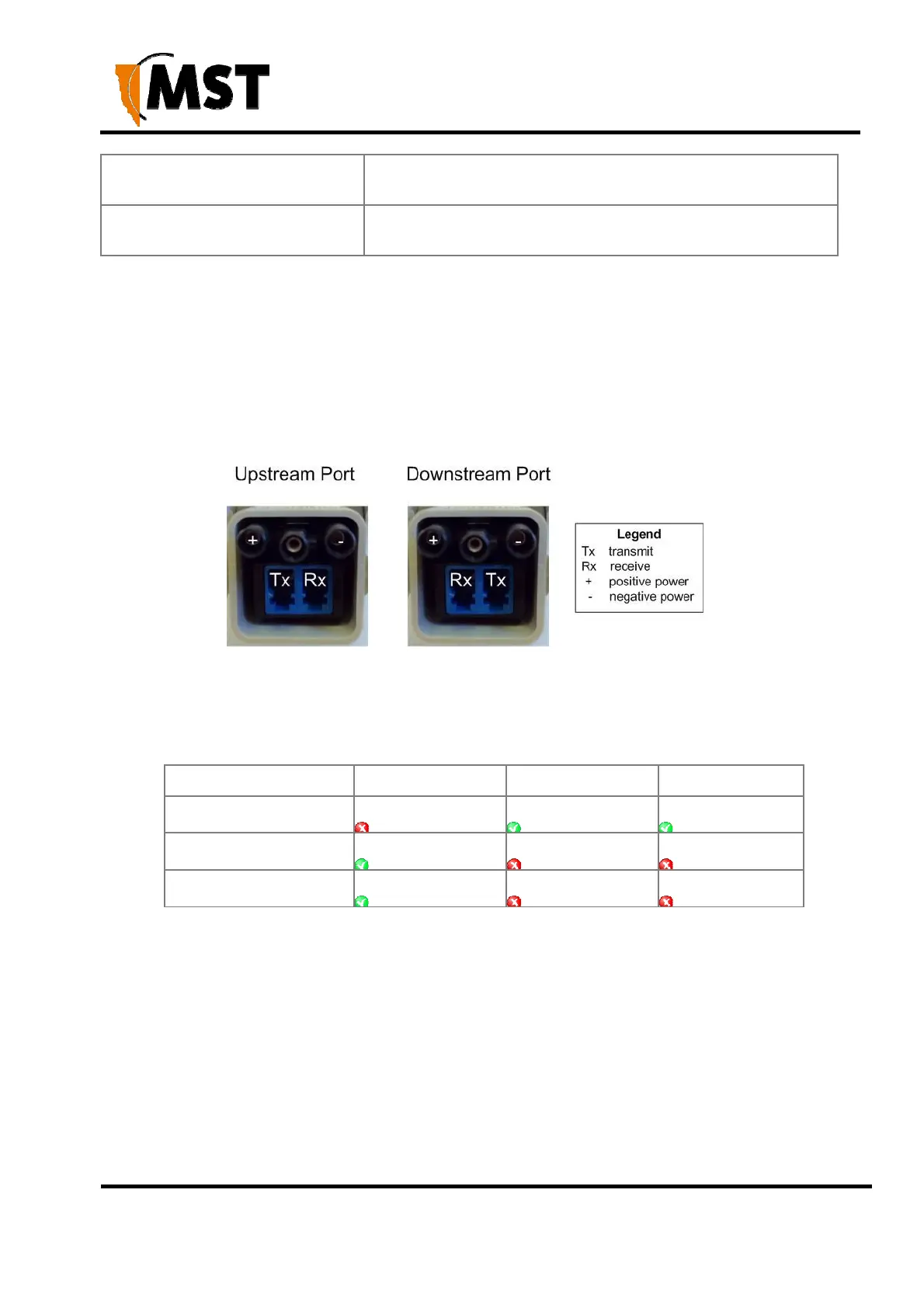
By default, port A is configured as the upstream port and ports B, C as the downstream ports. The
difference between upstream and downstream ports is the orientation of the fibre that is used for
transmitting and receiving data. This is illustrated in Figure 4: Fibre orientation of Upstream and
Downstream ports.
Figure 4: Fibre orientation of Upstream and Downstream ports
Due to the difference in the fibre orientation, MST composite cable and fibre optic cable can only be
connected between ports on AXON Core devices marked with a tick in the matrix below.
Port A Port B Port C
Port A
Port B
Port C
Single- and Multi-Mode Cables
AXON Core is supplied from the factory with 1000BASE-LX single-mode SFP modules. Customers
wishing to interface to other cable standards, e.g. 100BASE-FX single or multi-mode, should contact
MST to arrange replacement of the appropriate SFP modules.