XON Digital Plat
orm
User Manual
Revision A
14
2019 MST Global Commercial in Confidence
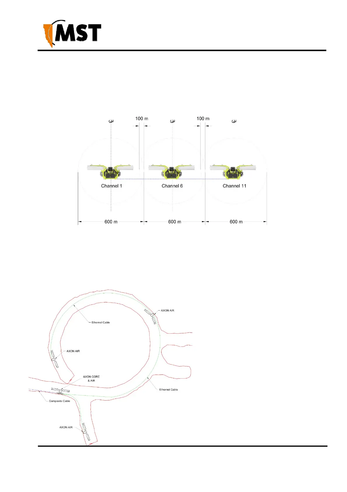
This ensures sufficient coverage between AXON Air units.
AXON Air units within range of each other must be configured with different Wi-Fi channels. By default
every fifth channel is used (channels 1, 6 and 11) to prevent signal overlap, minimising the possibility
of inter-modulation or interference. There are circumstances in which the configuration may allow all
radios to be operating on the same channel. Rapid handover and mobile device battery consumption
may improve in this configuration.
Figure 8: Wireless channel layout and distances around curves
In situation where line of sight (LoS) between the receiving device and AXON Air cannot be achieved
due to the physical layout of the tunnel, the distance between the AP’s may need to be reduced.
Below is a typical example of such situation. The AXON Air AP’s are spaced 100 m apart to
overcome the curvature of the spiral decline
There are many variances in a tunnel, which
influence the RF signal propagation, the size
and curvature being the most prevalent. The
surface of the walls, steel mesh, water and
objects in the RF path are all factors to take
into consideration when planning the system
design. Another important factor to consider
is movement of vehicles, large vehicle such
as trucks can shadow a large area of the
section of the tunnel, effectively blocking the
roadway and the RF path. In many cases, it
is advantageous to trial a section to get a
better understanding of the Wi-Fi
propagation in the specific environment. A
Wi-Fi survey is a good measure to insure
good coverage.