41
2019 MST Global Commercial in Confidence
XON Digital Plat
orm
User Manual
Revision A
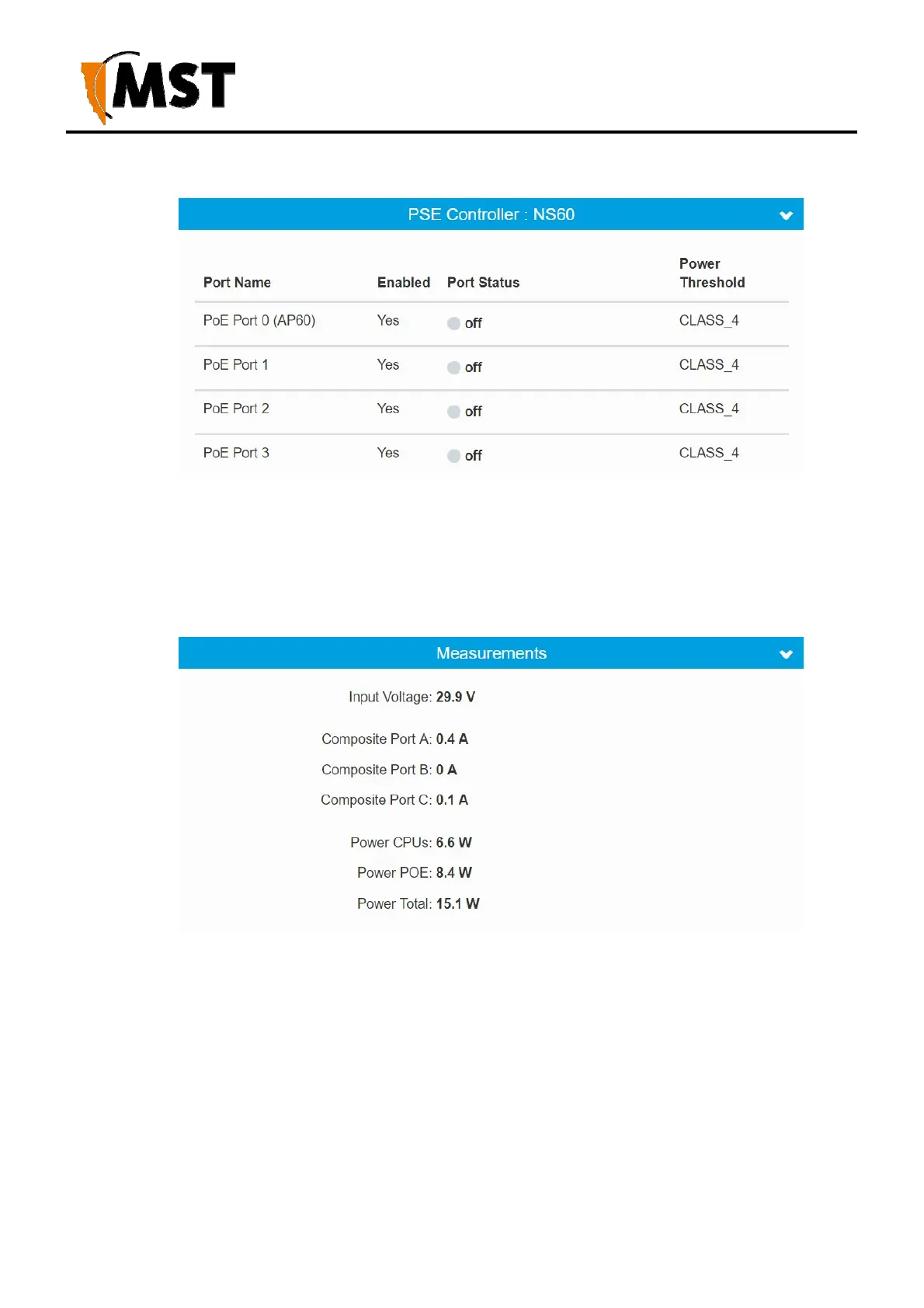
a. Each Controller
i. Port Name
ii. Enabled – Yes or No
iii. Port Status – Off (unplugged), Good (plugged in, powered), Failure (tripped, over-
current). In case of failure, additional reason for failed status will be shown
iv. Power Threshold – Currently negotiated CLASS for the plugged in device
b. Measurements
i. Input Voltage
ii. Composite Port A-C – Current flow through the composite port in Amps.
Positive value shows current entering, and negative value shows current
leaving the device.
iii. Power CPUs – Current consumption of the management CPU plus the
microcontroller
iv. Power POE – Current consumption of all POE devices including voltage
step-up / step-down overheads
v. Power Total – Combined total consumption for the whole AXON Core
device (CPUs + POE supply).