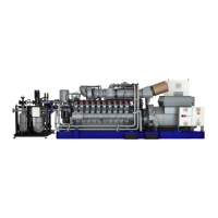
7.16.2 Engine control system – Removal and installation
Preconditions
☑Engine is stopped and starting disabled.
Special tools, Material, Spare parts
Designation / Use Part No. Qty.
Engine control system
1
Resilient mount
(→ Spare Parts Catalog)
NOTICE
Wrong engine governor installed.
Engine damage!
• When reassembling an engine, make sure that the governor with the data record for the given
engine is installed.
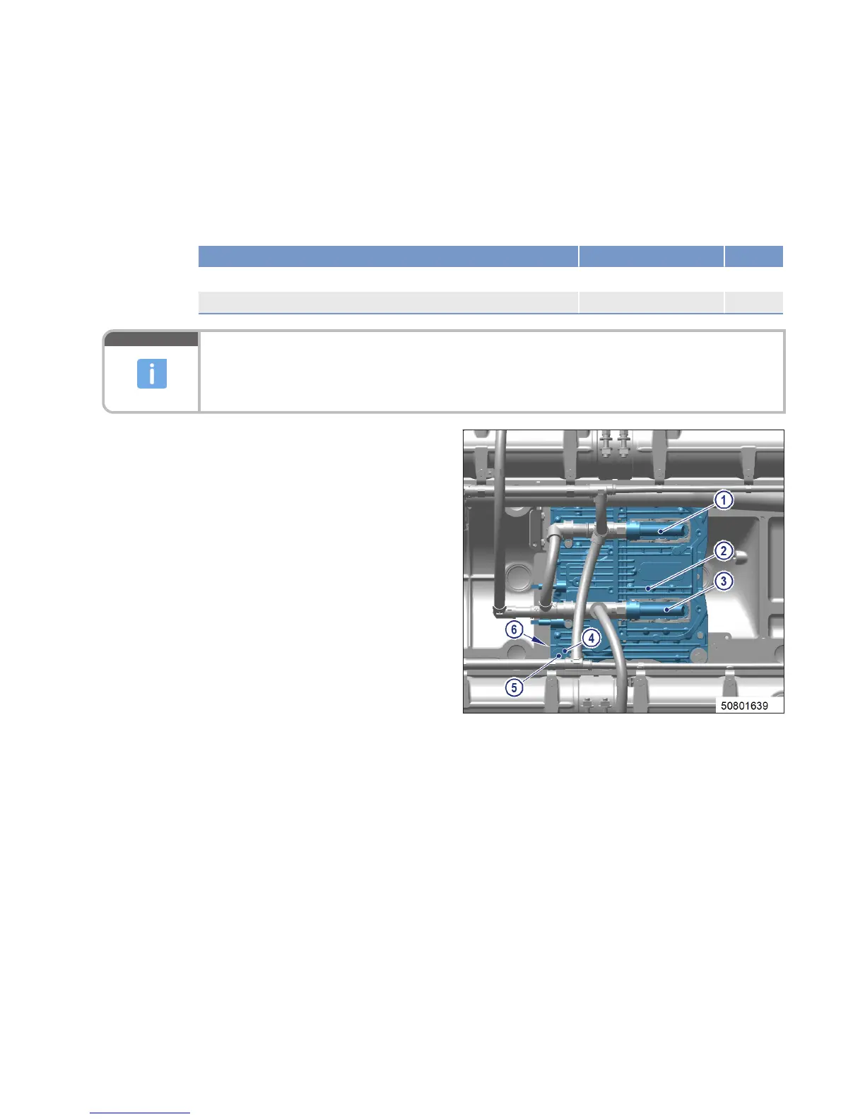
Removing engine control system
from engine
1. Note or mark assignment of cables and
connectors.
2. Release latches on connectors (1) and (3).
3. Disconnect all connectors.
4. Remove all screws (5).
5. Remove engine control system (2).
Installing engine control system on engine
1. Install in reverse order. Ensure correct assignment of connectors and sockets in so doing.
2. Check resilient mount before installation.
Result: Replace resilient mount if porous or defective.
MS150118/00E 2014-07
| Task Description | 129
TIM-ID: 0000053492 - 001