7.3.2 Cylinder head cover – Removal and installation
Preconditions
☑Engine is stopped and starting disabled.
Special tools, Material, Spare parts
Designation / Use Part No. Qty.
Torque wrench, 8-40 Nm
F30043446 1
Torque wrench, 0.5-5 Nm
0015384230 1
Ratchet
F30027340 1
Engine oil
Gasket
(→ Spare Parts Catalog)
Preparatory steps
u Disconnect wiring harness.
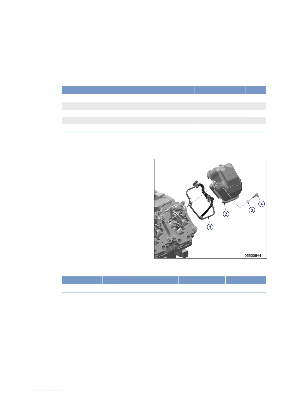
Cylinder head cover – Removal
and installation
Note: Before removing the gasket, release injec-
tor clamps and remove spade lugs.
1. Remove cylinder head cover (2) with gas-
ket (1) from cylinder head.
2. Clean mating face.
3. Check condition of gasket (1) in cylinder
head cover (2).
4. Replace gasket (1) if damaged.
5. Place gasket (1) in correct position on cyl-
inder head.
6. Push spade lugs under the terminals on the injector and tighten with torque wrench to the specified
tightening torque.
Name Size Type Lubricant Value/Standard
Nut M4 Tightening torque (Engine oil) 1.5 Nm ±0.25 Nm
7. Install cylinder head cover (2) with screws (4) and washers (3).
Final steps
u Connect wiring harness.
74 | Task Description |
MS150118/00E 2014-07
TIM-ID: 0000053452 - 001