Checking valve clearance at two crankshaft positions
1. Check TDC position of piston in cylinder 1 bank A:
• If the rocker arms are unloaded at cylinder 1 bank A, the piston is in firing TDC.
• If the rocker arms are loaded at cylinder 1 bank A, the piston is in overlap TDC.
2. Check valve clearance with cold engine:
• Inlet (I) = 0.3 mm;
• exhaust (X) = 0.4 mm.
3. Check all valve clearance values at two crankshaft positions (firing TDC and overlap TDC) according to
the table below.
Position Cylinder 1 2 3 4 5 6 7 8 9 10
12 V
Firing TDC in cylinder A1 Bank A I X I – – X I – – X – –
Bank B I – – – – X I – I X – X
Overlap TDC in cylinder A1 Bank A – – – X I – – X I – I X
Bank B – X I X I – – X – – I –
16 V
Firing TDC in cylinder A1 Bank A I X – X – X I – – X I – – – – –
Bank B I – – X – – I – I X I – I X – X
Overlap TDC in cylinder A1 Bank A – – I – I – – X I – – X I X I X
Bank B – X I – I X – X – – – X – – I –
18 V
Firing TDC in cylinder A1 Bank A I X I – – X I – – X – – – X – – – –
Bank B – X – X – – I X – – I X I – I X I –
Overlap TDC in cylinder A1 Bank A – – – X I – – X I – I X I – I X I X
Bank B I – I – I X – – I X – – – X – – – X
I
Inlet: Inlet valve adjustment permitted
X
exhaust: Exhaust valve adjustment permitted
–
Valve adjustment not permitted
Table 112: Valve clearance adjustments
4. Use feeler gauge to check the distance between valve bridge and rocker arm.
5. If the deviation from the set value exceeds 0.1 mm, adjust valve clearance.
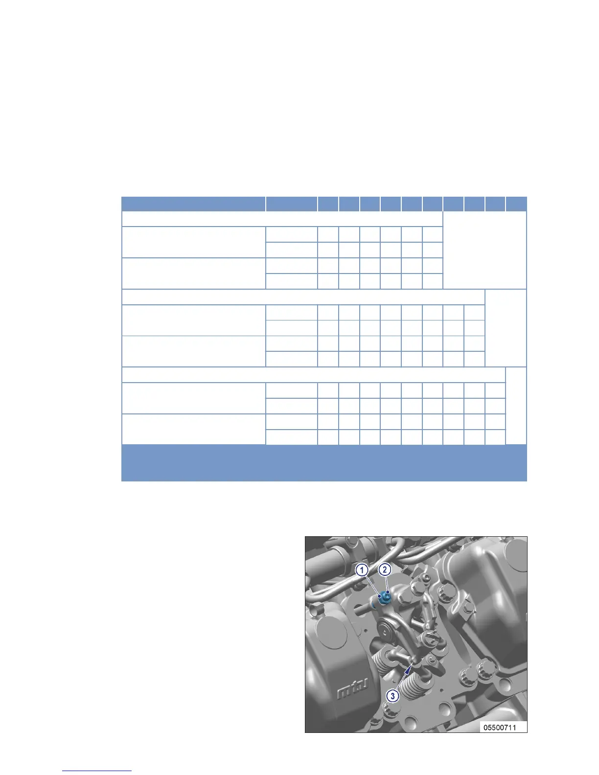
Adjusting valve clearance
1. Undo locknut (1) and unscrew adjusting
screw (2) a few turns.
2. Insert feeler gauge between valve bridge
and rocker arm (3).
3. Readjust adjusting screw (2) so that the
feeler gauge just passes through the gap.
4. Tighten locknut (1) with torque wrench to
the prescribed tightening torque of 50 Nm
while holding the adjusting screw (2) in
place with an offset screwdriver.
5. Insert feeler gauge between valve bridge
and rocker arm to verify that the gauge just
passes through the gap.
Result: If not, adjust valve clearance.
72 | Task Description | MS150118/00E 2014-07
TIM-ID: 0000053450 - 001