Chapter 1 – Safety Information and Product Description
Multi-Tech Systems, Inc. MultiModem® iSMS User Guide for Administrators 8
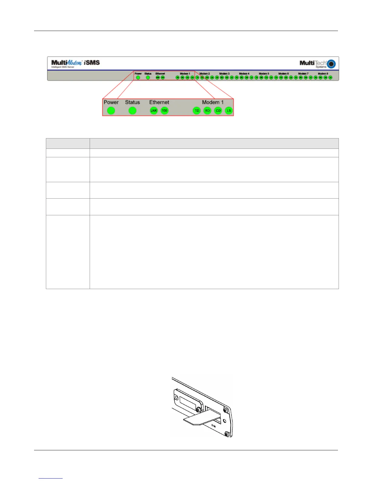
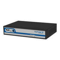
SF 400/800 Front Panel
SF 400/800 Front Panel LEDs
LEDs Description
Lights when power is being supplied to the MultiModem iSMS.
When functioning normally, the LED blinks. The LED is a solid light when the
MultiModem iSMS is booting up, saving the configuration, restarting, or updating the
firmware.
Ethernet
100
Lights when a successful connection to the 100BaseT LAN is established. Off when
connected at 10BaseT.
Ethernet
LNK
Lights when the LAN port has a valid Ethernet connection.
Blinks when it is receiving or transmitting data.
Modem n TD TRANSMIT DATA. This LED blinks when the modem is transmitting data to your
wireless carrier.
RD RECEIVE DATA. This LED blinks when the modem is receiving data from your
wireless carrier.
CD CARRIER DETECT. This LED lights when the modem detects a valid carrier signal
from a wireless carrier.
LS LINK STATUS. This LED flashes once evey 3 seconds when network registration is
succesful. This LED is on constant if the network registration is invalid, if a
network signal is not detected or if a SIM card is not installed in the modem.
SF 100 SIM Card Installation
A SIM (Subscriber Identity Module) card is required in order for the MultiModem iSMS to operate on a
GPRS network. To install the SIM card:
1. Remove power from the unit before proceeding.
2. Use a small screwdriver to remove the screw closest to the outside edge of the MultiModem iSMS.
Then swing the SIM slot cover up and over to the left.
3. Insert the SIM card into the SIM card slot. The following graphic shows a partial front panel
illustrating the correct SIM card orientation.
4. Swing the cover back to its original placement and replace the screw. Reattach the power supply.
Downloaded from Elcodis.com electronic components distributor