Do you have a question about the MUTOH SC-650 and is the answer not in the manual?
Introduction to the SC Cutting Plotter maintenance manual.
Legal notice regarding document reproduction and usage.
Information on potential radio interference and compliance.
Technical specifications for the SC-series cutting plotters.
Environmental conditions for optimal plotter operation and storage.
Explanation of the control panel buttons and their functions.
Wiring and component diagrams for SC-series and SC-550 models.
Configuration and pinout for the RS-232C communication interface.
Configuration and pinout for the Centronics communication interface.
Identification and classification of machine errors.
Common issues, their causes, and recommended solutions.
Introduction to diagnostic modes and required hardware.
Procedures for running diagnostics using the standard SC keyboard.
Procedures for running diagnostics with an optional LCD keyboard.
Guide to accessing and replacing mechanical components.
Procedures for replacing electronic parts and configuring settings.
List of specialized tools and adhesives for maintenance tasks.
List of part numbers for SC-series body and cover components.
Detailed parts breakdown for various assemblies.
Detailed technical specifications of the SC-series cutting plotters.
Guidelines for optimal operating and storage conditions.
Explanation of each function key on the plotter's control panel.
System block diagram for the first version of SC-series plotters.
System block diagram for the second version of SC-series plotters.
System block diagram for the first version of SC-550 plotters.
System block diagram for the second version of SC-550 plotters.
Details on the standard RS-232C serial interface.
Examples of serial cable wiring for connectivity.
Pin assignment details for the Centronics interface.
Information on errors that can be resolved by the user.
Information on errors requiring service intervention.
Troubleshooting by symptom and recommended solutions.
Introduction to diagnostic modes and necessary keyboards.
How to perform diagnostics with the standard SC keyboard.
How to perform diagnostics with the optional LCD keyboard.
Procedure for initializing the EEPROM settings.
Steps for performing the plotter aging test.
Tests to verify cutting quality using drawn patterns.
Procedure to measure and adjust cutting mat height.
Procedure for adjusting the sheet-off detection system.
How to create backup plots of user and adjustment parameters.
Memory check and checksum tests for EPROM and RAM.
Tests for control panel LEDs/keys and actuator functions.
Tests for motor drive, encoders, and polarity.
Tests for tool selection and paper handling.
Display of machine working time and cut distance.
Diagnostic and adjustment functions reserved for future use.
Procedure to calibrate the X-axis length accuracy.
Procedure to calibrate the cutting mat height.
Procedure to calibrate the pen force.
Procedure to adjust the sheet-off system for the cutter.
Aging test for the cutter's sheet-off system.
Adjustment function not utilized for maintenance.
Table indicating access points for part replacement.
Guide to accessing and replacing mechanical components.
Procedures for replacing electronic parts and configuring settings.
Specific steps for removing the left and right covers.
Steps for removing and installing the transparent cover.
Procedure for accessing the PCB box.
Steps for removing and installing the Y-rail cover.
Steps for removing and installing the grid cover.
Detailed steps for removing and installing the cutting head.
Steps for removing and installing the grid rollers.
Steps for removing and installing the long Y-drive belt.
Procedure to adjust the pressure of the pressure rollers.
Mechanical alignment steps for the sheeting off mechanism.
Procedure for removing and installing the main PC board.
Procedure for replacing SC-550 main and terminal PCBs.
Configuration settings for DIP switches on the main PC board.
Procedures for EEPROM initialization and replacement.
Procedure for replacing the power supply board on SC-series.
Procedure for replacing the power supply board on SC-550.
Details of power supply output connector pin assignments.
Procedure for removing and installing the terminal board.
Steps for removing and installing the keyboard unit.
Procedures for replacing the X-motor and drive belt.
Procedures for replacing the Y-motor and drive belt.
Steps for removing and installing the head flex cable.
Steps for removing and installing paper sensors.
Steps for removing and installing the transparent cover sensor.
Steps for replacing the pressure roller UP/DOWN sensor.
Steps for removing and installing the fan motors.
List of part numbers for SC-series body and cover components.
List of part numbers for the right cover and keyboard assembly.
List of part numbers for the left cover assembly.
List of part numbers for transparent cover assemblies.
List of part numbers for PCB box components.
List of part numbers for head flex cable assemblies.
List of part numbers for the pressure roller UP/DOWN mechanism.
List of part numbers for the X-motor assembly.
List of part numbers for the X-rail assembly.
List of part numbers for the Y-motor assembly.
List of part numbers for the Y-rail assembly.
List of part numbers for the Y-axis drive belt assembly.
List of part numbers for the Y-drive pulley assembly.
List of part numbers for the Y-axis return pulley assembly.
List of part numbers for the pressure roller assembly.
List of part numbers for the cutting head assembly.
List of part numbers for SC-550 body and covers.
List of part numbers for SC-550 right cover and keyboard.
List of part numbers for SC-550 left cover assembly.
List of part numbers for SC-550 PCB box components.
List of part numbers for SC-550 penhead flex cable assembly.
List of part numbers for SC-550 X-motor assembly.
List of part numbers for SC-550 X-rail assembly.
List of part numbers for SC-550 Y-motor assembly.
List of part numbers for SC-550 Y-axis drive belt assembly.
List of part numbers for SC-550 Y-drive pulley assembly.
List of part numbers for SC-550 Y-axis return pulley assembly.
List of part numbers for SC-550 Y-rail assembly.
List of part numbers for SC-550 pressure roller UP/DOWN mechanism.
List of part numbers for SC-550 pressure roller assembly.
List of part numbers for SC-550 cutting head assembly.
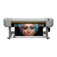
| Print Width | 64 inches |
|---|---|
| Ink Type | Eco-Solvent |
| Dimensions | 105" x 32" x 50" |
| Number of Colors | 4 (CMYK) |
| Media Types | Vinyl, banner, paper |
| Connectivity | USB |
| Media width | 64 inches |
| Interface | USB |
| Technology | Piezo Inkjet |