L NAPCO Security Systems
X GEM-X255 Programming Instructions
Page 19
WI1092E 10/05
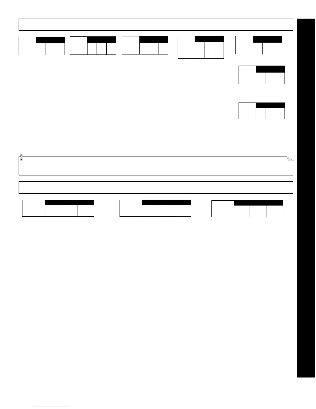
SYSTEM DELAYS & TIMEOUTS (ADDRESS 0000-0002, 2402, 2406, 2414 & 3902)
SYSTEM DELAYS & TIMEOUTS (ADDRESS 2407, 2408 & 4088)
SYSTEM DELAYS/TIMEOUTS
EXIT
ADDRESS 0000
DELAY
(sec.)
[Default = 060]
ADDRESS 0001
[Default = 030]
ENTRY
DELAY 1
(sec.)
ADDRESS 0002
[Default = 030]
ENTRY
DELAY 2
(sec.)
ADDRESS 2402
[Default = 000]
Aux.
Output
Access
Control
Timeout
(sec.)
ADDRESS 2406
[Default = 000]
ABORT
DELAY
(sec.)
ADDRESS 2414
[Default = 000]
Telephone
Line Test
Delay
(x15 sec.)
ADDRESS 3902
[Default = 000]
CS Telco 3
Report
Delay
(sec.)
WARNING: Timers have uncertainty of +/-1 sec, so a "time" of 1 second may actually timeout IMMEDIATELY.
Select delay/timeout (0-255 seconds).
EXIT/ENTRY DELAYS:
Apply only to zones programmed with the following options “Exit/Entry 1, Exit/Entry
2, Exit/Entry Follower”.
For UL Installations, the maximum exit delay is 60 seconds and the maximum entry
delay is 45 seconds.
NOTE: Sensor Watch Time Options are similar to above table, except in hours.
Press U or D to save.
1. Enter delay/timeout in corresponding address locations above.
Note: All entries for address 2407 are in quarter seconds (.25 seconds).
Therefore, the default of 008 results in a 2 second timeout.
2. Press U or D to save.
CHIME
ADDRESS 2407
TIME
(¼sec.)
[Default = 008 x ¼ sec. = 2 sec.]
AC Fail
ADDRESS 2408
Report Delay
(x10 min.)
[Default = 008]
ADDRESS 4088
[Default = 024]
Sensor Watch
Delay (Hr.)